The Bigger Picture of Cryogenic Cooling Costs

The Bigger Picture of Cryogenic Cooling Costs

First thoughts on cooling

Many people initially think of refrigeration compressors for cooling when product testing. Compressors work great for home refrigerators and sometimes they work the best for temperature chambers or thermal platforms as well. There are caveats but the main conditions where mechanical refrigeration systems work best are as follows:

  • Where the temperature is held steady for long periods of time.
  • Where cooling rate or getting to temperature quickly is not important.
  • When the lowest temperature range required is above -35C.

The hourly cost of consumption for cryogenic cooling using expendable refrigerants like Liquid Nitrogen or L-CO2 is indeed higher but in the big picture, often the total cost of running mechanical refrigeration is greater.  Several factors can contribute to the cost advantage of using Liquid Nitrogen.

  • The initial cost of cryogenically cooled equipment is generally much less due to the far lower complexity.
  • Productive thruput is generally greater due to the cooling speed of LN2 and often even reduces real estate square footage requirements dedicated to testing.
  • Simpler system design of LN2 systems directly relates to less money to maintain.

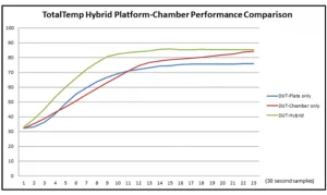
Within limits, speed generally = productivity. Ramping to temperature with mechanical refrigeration can be time-consuming.  The faster cooling times of expendable cryogenic coolants represent a large percentage of the ongoing savings using LN2 or CO2. More batches per day can be accomplished by reducing the requirement for yet more costly test stations, the space to keep them, and the energy to power them.  If your testing routine requires more temperature cycling pulldowns to cold temperatures or your devices are active/massive loads, the savings can be greater with Liquid Nitrogen cooling.  LN2’s superior ability to remove heat gives it the capacity to get cooling jobs done in favorable time frames.

While the efficiency of scale is to be gained with larger temperature test systems, benchtop systems with smaller batches can make sense too.  I am reminded of the theory of optimum carpooling partners which says If you carpool with one person, you cut your driving in half, you would have to carpool with everybody to eliminate the other half of the driving…  Not to mention the delays that would inevitably happen.  As I digress, the point is that a lot of time can be spent waiting to get many devices ready to undergo tests, thus holding up testing progress.

Cascade refrigeration systems used to cool to temperatures below -40C have had made strides towards improved reliability in recent years but are far more complex than single-stage systems, more expensive to buy, operate and maintain.  Another story here: When I worked at another thermal test equipment company, I remember being more than a little surprised when a contractor had performed warranty repair work on a refrigeration system at their shop. They had an amazingly large line item on the bill for “Electricity used by the unit while in the shop”.  Just how legitimate the charge was can’t be said but there is a significant cost that often is not seen or figured into ownership of refrigeration systems.

Actual costs of course will vary; load, profile other factors play into the decision.

We sell systems with mechanical refrigeration and systems with expendable cryogenic cooling so we don’t have too much agenda beyond helping you find the system that best suits your application.

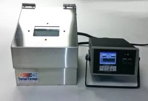
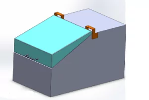
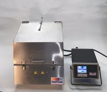
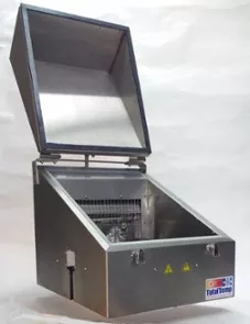
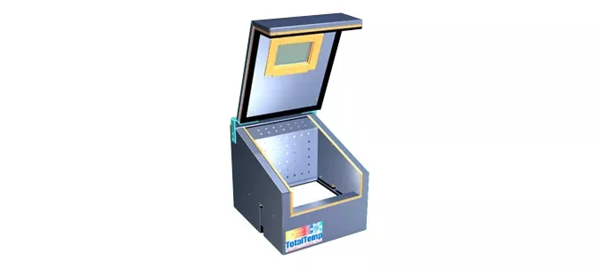
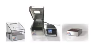
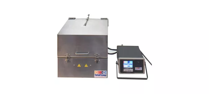
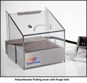
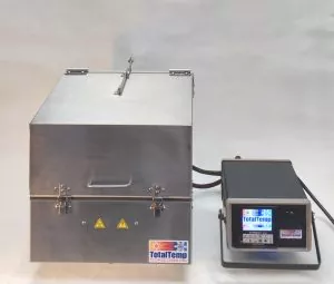
Small Hybrid Benchtop Chamber            Mechanically Chilled Hybrid concept


Several aspects of the overall cost of operation/ownership of mechanical refrigeration systems v. expendable cryogenic liquids are covered here, if you have any questions about general possibilities or your specific application, contact our engineers who are available to help you find the test equipment you require.

Thanks for reading and thinking about your thermal testing requirements.

Thermal Imaging Reveals Environmental Test Performance

Thermal Imaging Reveals Environmental Test Performance

The Smartphone-based (FLIR-ONE in this case) infrared imager is really useful for displaying very small relative temperature gradients. The Hybrid Benchtop chamber brings to your lab bench performance in the form of convenience, automation, and also thermal performance capabilities that are easily seen with these relatively inexpensive imaging tools.

On the left- at 5 minutes in the hybrid benchtop chamber set to 75°C, a thermal image of a computer hard drive as a Device Under Test (DUT) shows very good thermal uniformity.  On the right, the same part on just a thermal platform alone still gets the base of the part to temperature very quickly but shows larger gradients to the surface of this higher profile part given a similar timeframe.

Using just a chamber alone can achieve the same uniformity for this part however due to the limitations of heat transfer by convection, the time required to achieve good uniformity is much longer.  Often twice as long.

The Hybrid benchtop chamber gets parts to temperature faster like a thermal platform while minimizing thermal gradients of the parts like a chamber. The Hybrid design helps the thermal platform along with its many other advantages work effectively with higher profile parts.

Thermal platforms alone are often an optimum solution for a lower profile and active heat-producing parts.

Without the thermal imager in hand, temperatures are easily and automatically measured by the Synergy Nano Temperature controller at several points on the DUT thus confirming the speed and uniformity of the Hybrid Benchtop ChamberAdvanced temperature control algorithms (cascade PID loop) provide good benefits to speed up the process as well.

The Synergy Nano temperature controller controls a profile and logs any thermal testing results to local storage. At the completion of the test, the controller delivers the test results automatically.  It can use email to deliver charts and logs in PDF format directly to a network printer without a PC. This makes the whole process more efficient.

Temperatures can be measured at several points on the DUT to confirm speed and uniformity. Advanced temperature control algorithms (cascade PID loop) can improve the performance as well.

Thermal Test Engineers are becoming accustomed to a new level of thermal test performance with TotalTemp Technologies products.

Optimizing Thermal Testing on Hot/Cold Plates

Optimizing Thermal Testing on Hot/Cold Plates

Thermal Platforms are a great alternative to a temperature chamber for accessible benchtop thermal testing.  Keeping a few key points in mind will help make testing go as effectively as possible.

  • Good surface-to-surface contact.
  • Protect the component from air currents with a cover.
  • Since the temperature at the surface to optimize thermal performance and confirm low gradient results.
  • Use the best coolant for the application.

An economical thermal testing system, the thermal platform can be a great alternative to a chamber under many conditions.

Good surface contact is key, if your device does not have a flat thermally conductive surface, it may not be a good candidate for testing on a thermal platform.  Always make sure the surface contact is as intimate as possible without particles or gaps in between surfaces. mirror-smooth surfaces are best and thermal compounds always have some thermal resistance so a minimal amount of thermal compound is best to fill microscopic gaps in the contact surfaces.

Air currents can definitely cause thermal gradients to show up in testing.  A cover is always recommended to minimize gradients. Especially at extreme temperatures. The Hybrid benchtop chamber actively controls gradient with an independently controlled air zone above the platform but simple covers are often effective for reducing gradients.  An intermediate cost alternative is also our purge conditioner system with an internal heat exchanger that conditions the air before it enters the cover above the thermal platform.

Purge gas conditioning in / out shown top, center

Monitoring the temperature at the DUT or any specific point of interest verifies that the results are being achieved and also allows the use of advanced temperature control algorithms that can get the device to temperature more quickly and control overshoot in the process.

DUT temperature sensing block

Whether LN2, CO2, vortex tube, or mechanical refrigeration, for the available facilities resources, ramp rate, and range requirements TotalTemp can certainly help you make the right choice for your application. Call or Email us.

Temperature testing on a thermal platform can produce fast and convenient high-quality results with attention to these few details.  Automation features of the Synergy Nano temperature controller will also help you produce demonstratable results while meeting your thermal testing requirements.

Thermal conductivity: Compound, Sil-pad or nothing?

Thermal conductivity: Compound, Sil-pad or nothing?

Why use anything?   

Good thermal conductivity is important to the dissipation of unwanted heat from active power components and also important to the application of thermal platforms for testing electronics.

Perfectly flat, parallel and particle-free surfaces might show better thermal conductivity directly pressed together, however, some of the real-world realities generally prevent that best-case best performance. Here are a few reasons to use thermal grease:

  • Metal surfaces that appear to the eye to be perfectly flat, free of voids and parallel are usually are not.
  • Electronics like cleanliness, not all products can be built in clean rooms. A small unseen particle between two surfaces can easily prevent them from mating properly
  • Keeping even pressure on two surfaces is not always as easy as it might seem.  Keeping an appropriate amount of pressure on the two surfaces is important to transfer heat. Grease fills voids caused by uneven clamping pressure.

Thermal grease to the rescue?

So – given that close enough to perfect flatness, cleanliness, and parallels is hard to achieve, thermal grease has been used for decades to improve the thermal conductivity between two metal surfaces. Much has been said lately in the world of competitive computing & overclockers about heat transfer thermal grease.  Generally, the most important point is less is better. There are articles and stories reporting varying levels of improvement in heat transfer from different grades of thermal transfer grease.  In general, what I have seen says that the quality of the grease can make some difference and the high-end stuff is expensive but generally far from proportionally better.  One youtube video even suggested Nutella, the food product that worked about as well as much thermal transfer product. Well, I’d say don’t try that but is interesting that it could work at all, even as a short-term solution. I am pretty sure over time it would shrink and prove corrosive to metals to mention a few. Properly applied thermal compounds should have little risk of making a mess over the rest of the electronics or in general. This is also a good time to note that often electrical conductivity doesn’t matter that much but depending on the application, some thermal compounds are specified to be electrically conductive and some are required to be insulating. clearly, you wouldn’t want unwanted electrical conductivity on a circuit assembly.

Silpads to the rescue from messy grease.

Silpads and similar products are pretty much what the name says, silicone-based pads used in lieu of grease and designed to be either electrically conductive or not based on the application. They compress slightly to fill in voids and are often reusable providing faster, more repeatable results. Silpads are a good solution for many heat transfer requirements.  Due to their generally thicker nature, they are generally slightly less thermally conductive than a very thin layer of thermal compound.  When it is important to maintain electrical isolation, they are often better than other alternatives.

Actual “Flat” anodized aluminum surfaces at 200 X magnification

At 200x magnification, you can easily see that flat and smooth is really not flat and smooth. The one on the left might initially look and feel flat to the touch but in fact, it is not a good surface for thermal conductivity due to the voids.  This photo on the left is what the result would look like with a hard anodize treatment on cast aluminum (Cast metal generally has more voids).  Under a microscope the microscopic pitting is obvious.

The example on the right shows an acceptable surface for thermal conductivity however this is a view of a used thermal platform surface with a hard anodize that shows more true flatness as seen under the microscope but also shows minor wear scratches that can impede thermal conductivity.  A small area of missing material is not so significant but if a ridge or pockmark prevents full contact between the surfaces, it can greatly limit heat transfer.

If the surfaces can be lapped for improved flatness better thermal conductivity will clearly be achieved.

Keeping good, even force holding the surfaces together is the final note here.  It may seem obvious but in many cases, thermal conductivity is hampered by uneven pressure. Too much on one side or just not enough. More is usually better for better thermal conductivity with the limiting factors being most practical issues such as not distorting the surfaces which must have good contact.

CONCLUSION

Most surfaces are not as particle-free, flat, and parallel as they initially seem. A little thermal grease goes a long way to making for better conductivity, Silpads are less messy and also help cope with special needs such as electrical isolation and reusability but may have slightly lower heat transfer performance.  Use of thermal grease and silpads together is generally not recommended as you will end up with two layers between the surfaces. Finally don’t forget secure and even clamping.

Thermal Testing Results Delivered… to your printer

Thermal Testing Results Delivered… to your printer

Why is it important? 

Product testing takes time and requires careful tracking of results.  Thermal Platforms and Hybrid Benchtop Chambers with the Synergy Nano controller not only speed the thermal processes but also automate plotted results while avoiding chances for error. Thus easily producing meaningful data.

How do I do that?

The Application Note at the link here demonstrates how easily printed results from the Synergy Nano Controller can be produced.

https://www.tidaleng.com/appnotes/SCAP90.pdf

The temperature controller on these products can directly produce PDF files, email, or output directly to a network printer.

Automate your thermal testing with no-fuss printed results.

It clearly beats the old way

Wrapping it up

In addition to being a top-rated temperature controller with many other advanced features. These plotting features save time, produce fast and accurate documentation of your test results, via printer, PDF, email – or just viewed with a standard web browser.

It can communicate to any HPCL capable printer with an Ethernet port.

Contact TotalTemp or your local sales representative to find out more.

Thermal Stress Testing

Thermal Stress Testing

A thermal Stress Test can mean a few slightly different things.

Thermal stress we are talking about here is a form of testing applied in the design phase or production of most electronic devices when reliability is important.  It often is combined with other stresses such as power-up, operation at the margins of power, humidity, vibration, etc.

1) in the generic form, Thermal Stress Testing is any testing process that is used to verify the functionality or reliability of a device over a specified temperature range, presumably equal to or slightly more severe than what would be the range of operation expected in the field.  Also, see HALT or HAST testing which can include test-to-failure or quality verification of devices.

2) Thermal Stress Testing also can refer to an especially high rate of change temperature testing.  Used for the purpose of verifying reliability, and functionality over a range of conditions equal to or more severe than what the device would be expected to survive in use.  High rates of change are often associated with testing for the cracking of parts or material bonds. The term thermal shock is used to indicate a rapid rate of temperature change. Test requirements dictate thermal shock tests to simulate actual conditions of operation or tests that are designed to determine at what point stress causes a failure, in some cases well beyond what the product would expect to endure in normal operation.

3) Thermal Stress Testing can also apply specifically to testing where a device has two different temperatures applied.  An example of this kind of testing might be to simulate the conditions of an automobile electronic engine module with a cold-climate startup condition.

The new HBC144-N Hybrid Benchtop Chamber combines a small benchtop chamber with a 12″ x 12″ thermal platform for performance TotalTemp products, including the new Hybrid Benchtop Chambers are perfect for many types of Thermal Stress Testing.  Our standard thermal platforms can effectively perform rapid/repeated temperature cycling and verify at fast or slow rates as required.

The new Hybrid Benchtop chamber combines the gradient control of a temperature chamber with the speed and accessibility of a thermal platform.  This achieves better performance than either a chamber or platform alone. Hybrid benchtop chambers routinely cut thermal test times in half.

The Hybrid benchtop chamber also is especially capable of applying thermal stress of two different temperatures simultaneously applied to a device under test. For example, you can set the thermal platform to 150C and set the chamber above the platform to -40 to simulate the above-mentioned engine electronics cold-start conditions. Whatever your thermal stress test requirements are, TotalTemp can help you with the equipment to best meet your needs.

In addition to the thermal performance of the HBC144-N, the Synergy Nano Temperature controller has advanced temperature control algorithms that greatly enhance temperature testing speed and accuracy.  Automation features such as logging, remote control, web server, email status messaging, and network printing and can also save time and reduce errors over verification by manual methods.

Thermal Test Equipment, Fix it or Replace it?

Thermal Test Equipment, Fix it or Replace it?

The inevitability of Equipment Service | High-Performance Test Equipment

With the possible exception (almost!) of my old Honda S2000 most equipment, especially high-performance equipment will require service at some point. Relative to many other types of electronic test equipment, Temperature chambers, and thermal platforms have traditionally been remarkable for standing up to years or decades of grueling service while remaining reliable. In order of probability, I have seen the need for service to be

  1. Temperature controller fails or becomes obsolete.
  2. Compressor systems require service or.
  3. Cryogenic cooling solenoid valves eventually wear out.
  4. Everything else eventually.

New functionalities in automation and reporting seem impressive and may be worth the upgrade to something new but other than advances in Ethernet control there is not so much new I see on the front of test equipment or controller communication.  Many people have valid reasons for sticking with GPIB but after at least a decade of being sure GPIB is on the way out, it is still viable and we still support it. Modern serial to USB converters make it much easier now and cheaper to communicate with multiple instruments when the cost of GPIB is seen as prohibitive.

Repair costs, especially for on-site work are always painful. Fortunately, thermal platforms/controllers can generally be sent-in to vendors for service. Often a new controller is less expensive than a repair on old equipment. The goal frequently is just getting aging systems operational for minimal cost – be it repair or replacement. Sometimes the goal is “More brains” or higher performance is preferred.

In any case, TotalTemp offers new systems, repairs on competitive brands, retrofit controllers, or maintenance parts.

Call us or email us, we will take your call, and we have the experience and care to support your thermal testing needs.

Space Simulation with Small Portable System

Space Simulation with Small Portable System

Cost-Effective Space Simulation:

Space simulation adds another dimension to thermal testing.  In vacuum environments, heat is transferred by radiation or conduction since transfer by air currents (convection) is of course not possible without air. This is easily accomplished using thermal platforms in portable TVAC systems.

As is the case with temperature chambers, space simulation systems are often sized considerably larger than required due to a lack of knowledge of what future requirements will be. This results in several inefficiencies.

  • Portable space simulation equipment is cheaper to acquire
  • Smaller systems don’t take up as much valuable lab space to use and to store when not in use
  • Faster to pull down to vacuum and fast temperature transition times result in shorter test times required to perform tests
  • They are more efficient, using less power, generally not requiring special electrical services
  • Smaller systems are often more time-efficient as you are less likely to have to share with others. Larger systems often require travel, time-sharing, and waiting for a scheduled-use time

Conclusion:

Thermal platforms are a piece of natural test equipment for space simulation.

Consider TotalTemp Technologies thermal vacuum systems for full range testing:

Temperature range +150 to -75C. Vacuum 10-6 Torr.  For small to medium-sized devices. These thermal vacuum systems are flexible and fixture to meet many MIL-STD requirements.

Product Testing Takes Too Long

Product Testing Takes Too Long

Temperature control algorithm to expedite testing

Simple automation of thermal testing saves time and money

Capitol Equipment and Tech time are always expensive…  there are many costs involved with time spent waiting for a test to complete.  Waiting for temperatures to be achieved is a big part of the time required for the thermal test.  Frequently the time required for internal points of products to reach temperature is estimated, instead of measured. This ‘better safe than sorry approach often ends up unnecessarily extending the test time. It is a hedge against the flip side of erroneously reducing test times to less than what actually is required for internal temperatures to be achieved. Improperly cutting test time is also very costly. When failures that can be screened out with good testing make it into the field it is also expensive at many levels.

Modern temperature controllers can monitor one or more points of a Device Under Test (DUT).  This easily speeds test time by verifying when additional slower responding points actually achieve the specified test temperature.

Thermal platforms increase the thruput rate of tests, reducing test time, energy costs and time spent tying up expensive test equipment. Valuable time is also saved time for the techs who are monitoring tests. Easily setting up automated notifications and printing or filing of test results create time savings.

Since not all products have a nice flat conductive surface suited to testing on a thermal platform we introduced the Hybrid Benchtop Chamber that provides a ‘best of both’ solution, combining the universal capability of a temperature chamber with the conductive performance of a thermal platform.  Gradients are reduced and speed is increased as benefits from the combination. Advanced temperature control algorithms are employed to speed ramping time and verify that specific internal sensors achieve specified temperature set points.

Contact TotalTemp to find out more about our fast and efficient thermal testing equipment.

Conduction v. Convection for thermal testing

Conduction v. Convection for thermal testing

What are the trade-offs of heat transfer via conduction versus convection in regards to thermal testing?

Heat transfer via conduction is generally faster and more efficient. Depending on your purposes, conduction has some clear performance advantages and some limitations which we will talk about. In general, however, when appropriate conduction is often the best choice for performance.

More to the point, in this discussion, we are talking about trade-offs between a temperature chamber and thermal platforms. Temperature chambers are an example of forced convection.  Forced convection in a temperature chamber is achieved by the circulation of air using a fan.

Alternatively, natural convection is simply warmer air expanding and becoming less dense, naturally rising creating upward airflow with the colder air sinking to replace the heated air.  As a practical note, some chambers have very little forced airflow and thus are limited in convection heat transfer performance. On the other hand, increasing airflow excessively can produce unwanted heating by air friction and wasted money and energy spinning large blowers.

For completeness, briefly here, Radiation as the third main method of heat transfer is typically only used for a thermal test where conduction or convection is not so practical such as thermal vacuum testing of products with non-flat surfaces.

A popular example of a comparison between conduction and convection is the pot on the stove.

Courtesy NASA / Machine Design

Mostly radiation transfers heat from the burner to the pan, convection transfers the heat within the water with hotter, less dense water rising and cooler water sinking until temperatures equalize. Conduction in this example will cause your finger to feel the heat and maybe prevent you from picking up the pan.

In the example of a temperature chamber, a fan augments the natural convection flow with stirring action, greatly increasing heat transfer, to be more precise, this is process is often known as advection. The convective heat transfer in the air of a chamber is far less effective due to the relative density of air compared to water. This shows up as a much lower heat transfer coefficient in heat transfer equations.

For those who think more clearly in terms of equations, here is a simplified comparison of the math behind the heat transfer.

For Conduction:   Q = [k ∙ A ∙ (Thot – Tcold)]/d

Conduction is the direct diffusion of heat through a solid material

Q is the amount of heat transferred per unit of time

k is the thermal conductivity of the barrier

A is the heat transfer area

T-hot and T-cold are the temperatures of the regions for heat transfer

d  is s the thickness of the barrier

With Convection, the Equation looks like this:

Convection is the heat transfer between two items via moving groups of molecules

Q = hc ∙ A ∙ (Ts – Tf)

Where Q is again the amount of heat transferred per time unit

Hc is the convective heat transfer coefficient

A is again the heat transfer area

Ts and Tf are the temperatures of the surface and the temperature of the fluid (air)

These equations describe natural convection heat transfer, not assisted by fan or stirrer. The equations become considerably more complex and generally subject to heuristics and detailed modeling in order to achieve at least moderate accuracy. Variables such as calculating the barrier layers at surfaces, determination of laminar v. turbulent flow and general calculations based on the geometry of the air space fit into the equations. All that boils down to the generality that the more you can stir the air the better the heat transfer – however, it will never be as good as conduction. The kitchen example here is that you may be able to keep your hand in a hot oven for a couple of seconds without getting burned but just a few milliseconds of conduction will cause ‘cutaneous damage’ to your finger so with this you can see the relative rate of heat transfer with conduction and convection.

Besides burning your finger, conduction has its issues as well. While the Heat transfer coefficient, hc is the main limiting factor for heat transfer by convection, area (A) is the main limiting factor for heat transfer by conduction on thermal platforms.  Extra care must be taken as well to ensure that the area is really what you think it is(link).  Often voids or irregular surfaces limit the area of actual contact.

TotalTemp’s solution to optimal heat transfer is with the intelligent combination of both conduction and convection (advection) in our new Hybrid Benchtop Chamber.

Feel free to contact us with any questions concerns or interest in thermal platforms Hybrid benchtop chambers or any thermal testing equipment. We are always available with quality before and after-sales support.