Thermal Testing Limit Safety

Thermal Testing Limit Safety

Temperature Range Safety

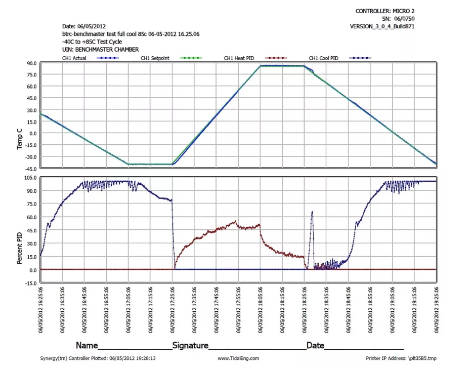
Temperature chambers and hot/cold plates are invaluable tools for environmental simulation thermal testing.

Inherent in their performance capabilities are some risks, primarily the possibility of exposing items (and people) to extreme temperatures resulting in damage, injury, or combustion. When testing it is obviously important to make sure devices or samples to be tested are not exposed to temperatures outside the intended temperature range.  In cases such as flight or space hardware the cost of disqualified hardware, even if it was only briefly exposed to excessive cooling alone can be enormous.

Several approaches singularly applied or redundantly will reduce the risk of losses.

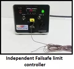
These systems are known by several names: Thermal Range safety, System Failsafe, Limit Controller, or Latching Thermostat, to name a few.  Some of these systems can be communicated with by automated test systems.

To start with, most modern temperature chambers or thermal platforms offer several levels of protection starting with the temperature controller.  Temperature controllers typically are designed to prevent users from requesting temperatures that would damage the system itself if not strictly the items under test.  Often there are locked limits that are set at the factory to protect the test equipment and additional user limits that can be set to prevent accidental damage to devices under test.  Beyond that many controllers will also go into an ALARM shutdown mode if the attached sensor reads outside the preset range.

The first way that requires thought of additional protection is for excessive or runaway heating. For example, if the output device that switches heaters sticks on, a controller alarm condition may not effectively stop runaway heating. Most systems include some sort of an additional latching thermostat that will shut down any heating when a limit temperature has been exceeded due to system problems, component failure, human error, or other causes.  The latching function keeps the heat from cycling back on if no human intervention in the form of a reset, power down, or other status confirmation has occurred.


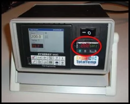
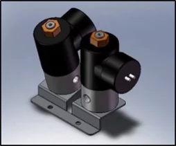
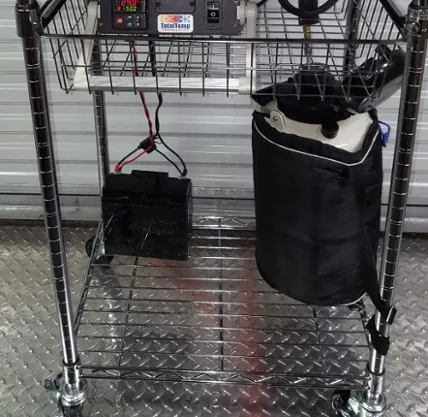
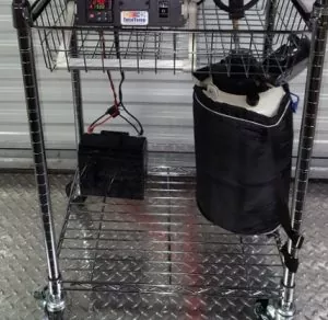
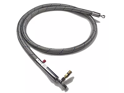
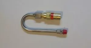
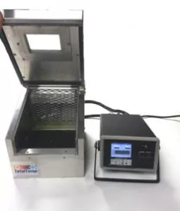
Failsafe Limit controller circled                Redundant L-N2 valve assembly

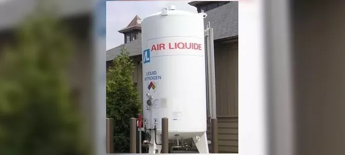
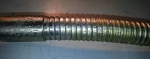
Systems that are air-cooled, or cooled with single-stage refrigeration are less likely to cause damage from runaway cooling conditions but often times protection from excessively cold temperatures are required as well.  If cooling is performed using L-CO2, multiple stage refrigeration, or especially if L-N2 then cooling limit protection is also highly recommended due to the extreme temperatures possible.  Many limit protection systems can respond to both high and low limits in one unit. Protecting from extremely cold temperatures when cooling with L-N2 will often require a little additional planning.  Unlike protecting from high temperatures, removing power from the system for a cold temperature runaway event is not as likely to provide full protection from cold.  The most common example of this would be contamination causing the plunger in the L-N2 valve to stick open.  Killing the power will not likely release the plunger.  For these cases, the addition of a redundant L-N2 valve wired to the limit controller is a good choice, especially if there is a possibility of unattended or overnight testing.  The redundant valve stays energized so it is not receiving the same operational wear and tear as the control valve.

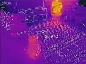
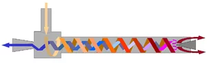
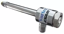
Following this thought, it is also good to look at the possibility of unintended heating due to an active load in the system or even high-velocity chamber blowers which can produce unexpectedly high temperatures. (well over 100C in the chamber is possible due to air friction alone, without the heat turned on!)  In these cases, it is good to ensure that functionality is in place to shut off possible active heat load sources in the chamber including chamber high-velocity blowers.  Keep in mind it works both ways. Blowers running after a shutdown will help cool self-heating products but also cause more heating due to air friction.

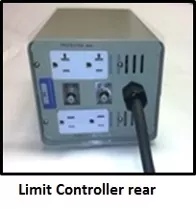
It is always a good idea to plan ahead when specifying new thermal test equipment. Existing chambers that don’t already have enough levels of built-in safety can often be retrofitted with integrated safety limit controllers that employ independent temperature sensing and internal system shut down capabilities.  If the addition of internal retrofit limit controls is not feasible, an external limit controller system can be employed to provide required levels of safety.  TotalTemp Technologies offers a variety of safety controls for hot/cold plates or chambers.


Selecting the Right L-N2 Coolant Delivery Hose

Selecting the Right L-N2 Coolant Delivery Hose

Expendable cryogenic liquids (L-N2 or L-CO2) deliver quick, accurate, economical, and precise cooling for testing electronic systems and components. Using the right hose will help make sure you get the best speed reliability and long-term economy out of your coolant.

.

Vacuum Jacketed Delivery Hose

Liquid Nitrogen is cold!   Approximately -180°C and it delivers the precise, powerful cooling capability for thermal platforms or other thermal testing equipment.  However, due to the extremely low temperature, losses due to poorly insulated hoses can result.  When specifying an LN2 delivery hose, use a vacuum jacketed hose and the shortest comfortable length possible to minimize losses.

Liquid from the tank vaporizes immediately when it hits the warm hose and wastes time and cooling potential.

A good quality vacuum jacketed hose provides benefits in several ways

1)  Vacuum insulation, like that used for the tank is the best insulation possible to reduce losses due to the extreme temperature difference between the coolant temperature and the ambient temperature hose.

2)  Unpredictable delays are often experienced while coolant is flowing and waiting for the hose to cool down.  More predictable cooling rates of a good supply of coolant will make it easier for control algorithms to function resulting in less delay or instability of temperature.

3)  Pressure can increase several hundred times as a liquid warms and tries to vaporize in a hose that is shut off at both ends.  Quality vacuum jacketed hoses will have a built-in pressure relief valve that relieves excessive pressure that could result in unsafe pressures if a hose is shut off at both ends or from other overpressure situations.

4)  Most factories have rules about the safety hazards of water on the floor.  Less condensation on L-N2 lines is safer too. With poorly insulated non-vacuum jacketed hoses, extremely cold or long-term testing can result in frost or condensation on the L-N2 plumbing which usually ends up like water on the floor.

If usage is short-term or very intermittent, an armored, non-vacuum jacketed hose may be called for as a cost-saving measure but in most cases, the above benefits of a good quality vacuum jacketed hose are worth the extra cost.

While on the subject: a few points to know about vacuum jacketed hoses

Delays due to vaporization in the hose are worse at lower L-N2 pressures.

Be gentle, dropping or otherwise slamming a vacuum jacketed hose can result in a tiny amount or complete loss of vacuum.

If a hose shows signs of lost vacuum (sweating) –

Sweating Vacuum Jacketed hose shows loss of vacuum

it can usually be re-evacuated to make it perform properly again.

Factory tools and equipment are needed to re-evaluate and test the vacuum seal

The Pressure Relief Valve (PRV) is there for the L-N2 safety of people in the lab, don’t alter or remove it.

Pressure Relief valve with Candycane Riser

The pressure relief valve works best when the outlet is pointing generally downward.  This reduces the chances that the valve may weep, leak or stick open if it should become icy. A candy cane riser is an optional J-shaped pipe nipple that allows the proper orientation of the PRV.

When a tank will be used later, it is generally better to leave the liquid valve at the tank ON, that way the warming, vaporizing, and resulting pressure increase will return to the tank and not unnecessarily cause the Pressure Relief Valve to vent.  The PRV is there to help improve safety but it is best to not rely on it. Pressure generally will climb over 400 psi. before the valve opens. The solenoid valve on a typical hot-cold plate or chamber will in most cases not open properly at this pressure.

CONTACT US

Please reach out with any questions you have regarding LN-2 delivery hoses or hot/cold plates, temperature chambers, or other thermal test equipment!

Spot Cooling with Vortex Tubes – a Viable Option

Spot Cooling with Vortex Tubes – a Viable Option

When using temperature chambers or thermal platforms to do thermal testing, the heating of devices tends to be more or less straightforward. Generally, electrical resistance heating, be it conductive or convection (or even radiant) is the best, cheapest, and most easily controllable method.

However when it comes to cooling, there are a few more options, the primary ones being mechanical refrigeration, expendable cryogenic gas such as L-CO2 or L-N2,  Peltier (thermoelectric), or – for some, generally smaller applications, vortex tubes are also an option.

Not to be confused with ordinary Venturi tubes, the official name of the device is the Ranque-Hilsch vortex tube.  These clever devices are able to provide a surprising amount of refrigeration capacity from compressed air alone.  They are best for small lower-cost spot cooling applications since they are a lot simpler and easier to maintain than refrigeration systems. They are somewhat less efficient at cooling than a typical refrigeration system.  Efficiency is comparable to Peltier cooling.

The summary description of the operation from Wikipedia:  Pressurized gas is injected tangentially into a swirl chamber and accelerated to a high rate of rotation.  Due to the conical nozzle at the end of the tube, only the outer shell of the compressed gas is allowed to escape at that end.  The remainder of the gas is forced to return in an inner vortex of reduced diameter within the outer vortex…

The main physical phenomenon of the vortex tube is the temperature separation between the cold vortex core and the warm vortex periphery.  The vortex tube is essentially a rotors turboexpander.   It consists of a rotor’s radial inflow turbine (cold end, in the center) and a rotors centrifugal compressor (hot end on the periphery).  The work output of the turbine is converted into heat by the compressor at the hot end.  This explanation of the heating/chilling effect stems from the law of energy conservation.

For the practical application, a small vortex tube with 100 psi room temperature air and an available flow rate of 5-10 SCFM can produce a temperature drop of 50 degrees C and removal of 2800 BTU/Hr., or around 800 Watts.

A couple of realistic concepts and limitations to using vortex tubes:

1.  Air source must be clean and of good capacity per above, this will enable long life with little or no maintenance

2.  Use of proper muffler is suggested to minimize exhaust noise

3.  Small active loads on cold plates or chambers will work well with vortex tubes

4.  Systems can be optimized for more capacity or more temperature differential.

5.  Properly integrated into a hot-cold plate or small chamber, a vortex tube chiller may be the best choice for small low capacity cooling needs.

TotalTemp Technology is happy to talk with you about your thermal testing requirements.

Feel Free to reach out with your questions.

RTD’s v. Thermocouples, which is best?

RTD’s v. Thermocouples, which is best?

RTDs v. Thermocouples

The question is often asked, “what is the best temperature sensor for my temperature testing or environmental testing application?”

The answers can vary a lot but the two main leaders of the pack are RTDs (Resistance Temperature Detector) followed by Thermocouples.

If you are looking for the short answer of which is best, it is RTD’s but here is a little more to the story

The primary reasons RTD are best:

Better long-term stability, more linear response, More gain- that is more signal change for a given temperature change, also they have easier to manage lead wire connections.

So why would someone choose a Thermocouple over an RTD?

Arguments in favor of Thermocouples:

The number one reason – Thermocouples are cheaper.  Market demands often dictate cheaper.

Thermocouples generally hold up better in environments of severe vibration or thermal shock.

They typically are better for point sensing instead of sensing a larger area or air temperature.

Stepping back a little: There are more tradeoffs, but those are the main considerations. To be fair, there are other viable temperature sensors for many applications but just a short history lesson first. German Physicist Thomas Johann Seebeck first discovered in 1821 that any junction of dissimilar metals will produce an electric potential related to temperature.  Thus the name for a device that senses temperature by the coupling of two metals.  The result was the first electronic temperature sensing device and it could be designed to work without any external power source. A couple of issues about how this sensor works are: 1) The carefully controlled types of metals in the sensor used have to be continued all the way to the instrument that is measuring the temperature. 2) The instrument itself requires an additional thermocouple to be used as a fixed reference.  Since the temperature of the fixed reference usually changes, often an additional RTD or bandgap sensor is used to compensate for the thermocouple calibration.

In 1871 Sir William Siemens discovered the Resistance Temperature Detector or RTD.  He found that Platinum wire and other materials have a well-defined relationship between temperature and the electrical resistance of the material.  The relationship between temperature and ohms is much more linear and easier to work with than the relationship between volts and temperature with thermocouples.

Thermistors are simply a specific type of RTD, often made with a polymer or cheaper materials than Platinum.  They typically have a narrower temperature range and have less long-term accuracy. Also as a side note, Thermistors most often but not always have a Negative Temperature Coefficient (NTC), meaning that they have less resistance as temperatures get higher.  This feature makes them handy for several special compensation applications, for example canceling out other factors that increase with temperature.

The Bandgap (transistor) Temperature Sensor is one other significant, modern temperature sensor.  This device makes use of the known effect that the forward Base to Emitter voltage of any transistor is directly and predictably affected by temperature.  These devices although rarely used in applications such as temperature chambers are popular because they are inexpensive and can be easily integrated into other silicon circuits making internal component temperature sensing very simple and affordable.  Their usability is primarily limited to the range of -40C to +200C.

RTDs are widely accepted as the preferred temperature sensor for long-term repeatability.  It is my position that they will continue to prevail as “the best quality sensor” however I do hear some interesting reports that there have been recent improvements to the technology of making and reading thermocouples.  I think the jury is still out but I would be interested to hear what experiences others have had with a so-called new generation of thermocouples and available accompanying 24-bit A/D sensing circuits.

As a final note, there are several distinctions between types of thermocouples and likewise different types of RTDs.  The thermocouple type must match the type the instrument is configured to read.  In the same manner, the RTD must match the curve (Typically DIN curve) the controller is configured for.  Additionally, the RTD has a base resistance value that must match controller configuration (typically 100 ohms at 0C)

If you want to know more, just ask.

TotalTemp Technologies offers a selection of 100 and 500 ohm RTDs and thermocouples for thermal platforms and other applications.

Our experienced team can provide assistance with your temperature sensing, hot/cold plate controlling, and thermal testing needs.

Thermal Testing with Convection and Conduction… together at last!

Thermal Testing with Convection and Conduction… together at last!

A Marriage Made in Heaven?
[Who could know, but now we do]

The Hybrid Benchtop Chamber – True Thermal Testing Bliss

Combines Thermal Conduction and Convection
in one incredibly fast and efficient design

A heartfelt Congratulation is in order for the happy and successful union of two distinct thermal testing methods that are finally sharing the same dance floor together – as the first true Hybrid.  To better understand the specific benefits from both sides of this collaboration of two testing methods, please review the following white paper:

Conduction vs. Convection for Thermal Testing

Typical Environmental Test Equipment used for Thermal Convection and Thermal Conduction

Thermal testing by convection is usually achieved with the use of a Temperature Chamber.  For versatility, standard chambers are very popular and meet the needs of a lot of testing purposes.  Chambers provide performance regardless of the shape of the device under test, are typically slower transitioning and settling, and require more lab space.

Temperature Chamber

Thermal testing by conduction is most commonly done on a Thermal Platform.  Platforms control temperature by conductive heat transfer and thus are inherently faster however are restricted to devices that have a flat conductive surface or can be fixtured to work on a platform.  Platforms provide fast-cycling time, require little laboratory real estate, and offer very good accessibility to test objects.

Thermal Platform (Coldplate)

Hybrid Benchtop Test Equipment Solves Many Problems

* Improves thermal uniformity gradients

* Increases throughput with faster cycle times

* Small footprint with easy access benchtop operation

* The fully-featured Synergy Nano Temperature Controller is capable of controlling platform temperature and air temperature independently or together

* Controller offers DUT and other data logging, remote access, cloud capability, and many networking functions

Click here: Hybrid Benchtop Chamber Page

Hybrid Benchtop Chamber Test Equipment

Shown with Lid up revealing the Thermal Platform floor of the Chamber

Thermal testing is an important part of electronic manufacturing for reliability and design verification.

There are a variety of products for thermal testing and now TotalTemp is presenting a completely new and unique contender.

Temperature chambers, thermal platforms, air forcing units, and liquid baths have been around for a while and work well with many types of testing requirements.   But the Hybrid Benchtop Chamber Test Equipment provides many of the best features of Temperature Chambers and Thermal Platforms together to maximize performance and control and shows new promise of filling the need for faster, superior thermal testing.

Hybrid Benchtop Chamber Has Performance Results

As shown in the data chart above, in the basic operation mode, The Hybrid Benchtop Chamber demonstrates a significant improvement in thermal test performance.  The floor of the chamber is a completely functioning Hot/Cold Plate and operates independently or in conjunction with the chamber.

Because the controller is capable of advanced temperature control algorithms, it can allow even better performance by monitoring DUT temperature and allowing air and platform temperatures to be carefully controlled while verifying that required DUT temperatures are achieved.

The standard model currently available is called the HBC49-N with a thermal platform size of 6.5” D x 7.5” W, the chamber interior dimensions are  8.5” W x 7.5” D, Height is 4.5” to 6.5” at the rear.  The system can be cooled with liquid nitrogen (L-N2) or liquid carbon dioxide (L-CO2) and is rated for a temperature range of -100°C to +150°C.

TotalTemp Technologies is the manufacturer of the Hybrid Benchtop Chamber.  TotalTemp is a manufacturer of temperature cycling and conditioning equipment.  They are located in San Diego, CA.

Calculus v. Statistics is it an Ongoing Battle?

Calculus v. Statistics is it an Ongoing Battle?

Which is more useful? Which is more significant to science and business or civilization?

I believe calculus has to come first but I don’t really think either is better.  This is my opinion. Both have their own appropriate applications and end goals.

Just a quick high-level review and opinion refresher here…

Calculus is Deterministic, if you need to plot a course to Mars, you would use calculus.

Statistics is Relativistic. Statistics would be used more to decide where you would want to land on Mars.

Vs. 

According to Wikipedia Calculus is the mathematical study of change as Geometry is the study of shape and algebra is the study of operations and their application to solving equations.

The study of Calculus has two major branches; differential calculus (rates of change and slopes of curves) and integral calculus (accumulation and area under a curve)

Statistics on the other hand is about the collection, all aspects of analysis, interpretation, presentation, and organization of data.

The two main branches of statistics are  1) Descriptive statistics which is about quantitatively describing or summarizing the main features of a collection of information or the quantitative description of the data itself.  Concepts like the mean and the standard deviation are the realm of Descriptive Statistics. and 2) Inferential statistics are used to infer properties about a population of data: this includes testing hypotheses and deriving estimates. The population is assumed to be larger than the observed data set; in other words, the observed data is assumed to be sampled from a larger population which attempts to infer propositions.  Point estimates and interval estimates are the realms of Inferential Statistics, according to Wikipedia, interval (Statistical) estimation is the use of sample data to calculate an interval of possible (or probable) values of an unknown population parameter, in contrast to point estimation, which is a single number.

Calculus is used in every branch of science, computer science, (even) statistics, engineering, economics, business, medicine, and in other fields wherever a problem can be mathematically modeled and an optimal solution is desired. It allows one to go from (non-constant) rates of change to the total change or vice versa. Often studying a problem where we know one and are trying to find the other related data.

Statistics helps us find truths or trends in the mountains of data we produce, often reducing the need to do Calculus on each and every alternate possibility.

People often lean towards one or the other as a preference but I think there isn’t really a battle of one being better than the other.

Personally, I prefer Calculus for its deterministic nature. Maybe also due to being exposed to more of it in school and work. If I had to choose one it would be Calculus.

As a final comparison on the more practical level in my work, Calculus is used to design the circuit; Statistics are used to determine the most effective testing of the product functionality and reliability before shipment.

Both apply if you are doing product testing.  If you are thermal testing in temperature chambers or on a thermal platform, you might be verifying a design built on Calculus or using Statistics to ask the questions and get answers about the yield on your production.

Cryogenic Cooling Safety

Cryogenic Cooling Safety

Liquid Nitrogen (L-N2), Liquid Carbon Dioxide L- CO2) and other cryogenic coolant coolants have potential risks but can easily be safely managed like many things in the lab. The effective and rapid cooling these fluids produce is a great convenience for thermal testing.

Similar to other potential hazards such as flammable liquids, electricity, hot surfaces, chemicals, etc. Cryogenic fluids can be safely used when aware of a few basic precautions.  The main precautions are as follows:

  • The extremely cold temperatures of cryogenic liquids can cause burns.
  • Pressurized liquids and gasses require proper pressure regulation/venting.
  • Tanks are often very heavy and pose risks should they fall over.
  • In extreme cases, excessive use can displace breathable Oxygen in the air.

Taking Proper Precautions

When making or undoing connections to cryogenic fluids, always wear gloves and eye protection.  Preferably heavy leather gloves full face shield.  In General, the rule is hands-off of plumbing and devices at cryogenic temperatures.

Be aware of the controls/safety features of any cryogenic liquid delivery system. Know how to use these controls. Locate safety vents or ruptured disks that might unexpectedly produce a stream of cold vapor.  Here is a supplier’s link with more detailed LN2 safety information and an explanation of the controls on a cryogenic liquid vessel. Tanks have many built-in safety devices to prevent over-pressurization and general safety.

Never tamper with any of the safety devices on a tank and do not adapt connections other than standard LN2 designated connections. Not just your eyes and flesh but many items in the lab become damaged or behave differently at these extremely cold temperatures. For example, typical foam pipe insulation from materials such as polyethylene becomes extremely brittle and shatters at temperatures of Liquid Nitrogen which is typically -185 C.

Be aware that cryogenic liquids expand dramatically and forcefully in the process of use and also during unintended vaporization in the hose. When connecting equipment to a source of cryogenic liquid, there is often an automatic valve at the downstream connection that is normally closed.  After the system is used and the operator believes that he is safely shutting off the coolant source at the tank, an unsafe condition can be created. With a closed valve at both ends of a liquid-filled hose, the increasing pressure as the liquid warms can rupture the hose. The hand valve at the tank should only be closed when you are sure there is no cold liquid in the hose.  For this reason, our LN2 hoses employ a pressure relief valve that will limit the maximum pressure to a safe level. Likewise, any device using coolant must have a functioning exhaust to vent the spent coolant.

The contents of high pressure (~900psi) CO2 tank are stored at room temperature so although the pressure is much higher in the hose, to begin with, it does not increase as it sits in the hose.  You can close the hand valve on a CO2 tank at any time without risk.

LN2 tanks or dewars as they are known (vacuum insulated thermos-like bottles) rarely tip over due to the wider base but must be placed on a stable level footing. Slimmer High-pressure CO2 tanks are more prone to tip over and must always be restrained when stored in the lab for even short periods of time. The valve on the top of the tank can break if the tank falls over and cause very dangerous situations. LN2 tanks typically have a steel “halo” around the controls and ports at the tank. This increases the safety of many tank accidents.

CO2 and LN2 are both non-toxic and large parts of what we normally breathe.  Use of these cryogenic fluids in a normally ventilated area is not a problem however if the ventilation is abnormally low or there is a very large amount of coolant being used, an Oxygen monitoring device should be used to monitor the Oxygen level in the room. Exit the room without delay if Oxygen levels go below 20%.

CONCLUSION

Cryogenic coolants like many things in the lab are easily handled in a safe and efficient manner by paying attention in general and being aware of a few basic concerns.

Cost effective wide range thermal testing

Cost effective wide range thermal testing

Testing at extreme temperatures requires considering several options. Testing at hot temperatures has its issues, however, testing at ultracold temperatures – below -40 C in most cases requires the use of expensive and sometimes failure-prone cascade refrigeration systems or alternately applying expendable cryogenic fluids such as liquid nitrogen or liquid CO2.

High-performance cooling is often more of a challenge than heating and also tends to be the least understood process.  The high initial cost is a well-known roadblock to acquiring the best equipment to do the job. Often the unknown or under-reported cost of running a refrigeration system, electricity, maintenance plus possible downtime also require consideration. When thinking of expendable coolant solutions, facilities managers often have some pushback to pressurized liquid Nitrogen or other cryogenic fluids.  Cryogenic fluid distribution systems can be another convenient and safer alternative to large tanks. Unless there are consistent and large-scale uses they are often not warranted due to the extreme installation costs.


10-liter tank on a lightweight portable cart

These safe and effective portable systems solve many Cryogenic Temperature testing requirements.

Moving Forward

Another often overlooked option for testing at extremely cold temperatures is a low-pressure Liquid Nitrogen system. I am referring to is a small portable low-pressure LN2 tank. For example, if you have a 20-liter portable tank you can carry the tank easily by yourself or transport it on a light-duty cart. It will store (with some loss) for well over a month, and best of all you can hold a thermal platform at any other similarly efficient (if it is such) thermal testing system at -50C for hours or ramp to -50C several times without refilling or swapping tanks.   Doctor’s offices often use small portable LN2 tanks with just enough pressure to make the Nitrogen come out of a nozzle.  Similar systems can be used to provide cryogenic cooling to small chambers or thermal platforms.  Sometimes these systems can safely have their pressures boosted by a small amount to achieve really good performance.

New technologies are helping Liquid Nitrogen generating systems be more widely available. Systems such as Elan2 products make homemade LN2 a cost-effective, efficient cryogenic cooling strategy.

Contact us if we can help with any concerns you may have about cryogenic cooling for environmental testing.

Evaluating Thermal Imaging for Temperature Test

Evaluating Thermal Imaging for Temperature Test

Initial FIndings

We acquired a FLIR ONE for Android from sources online, they are about $250 in most places. So the question is Toy or valuable tool. My opinion is Both! Not to deny the fun factor, (it is important to enjoy your job, right?) I say very much more on the useful tool side.  In the 90’s we paid more than that just to bring our products to a facility that allowed us to do some brief tests with less conclusive results. Laboratory grade thermal imagers still have a comma in the price tag and go upward from there.  This unit is primarily marketed as an uncalibrated tool but I found that the Flir One gives some very useful relative readings for testing and evaluating purposes.  As for absolute temperature readings, there is still a little something to be desired. The unit’s instructions are a little vague regarding measurement accuracies but the on-screen spot reading is quite useful.  The FLIR One unit offers better image quality and measures tenths where other units such as the Seek Compact thermal imager show readings with less precision.

Emissivity is an important factor in thermal imaging. Per the Wikipedia link here, emissivity is the effectiveness of a surface in transmitting energy as thermal radiation.  A cat would have very low emissivity whereas a black anodized aluminum surface would have nearly 1.0 emissivity. Professional grade and Non-imaging handheld thermometers all struggle some with emissivity. This unit has four different emissivity settings.

Useful Findings

For our Thermal Platform Business as you might expect it is useful in demonstrating the advantages of the thermal platforms and our Hybrid Benchtop Chamber over other environmental test equipment or thermal testing gear.

Examples here show a Thermal Platform heating up with locations of heaters evident and then a few seconds later stabilized at a hot temperature.

Thermal Platform heating to the temperature

In this case, further adjustment of the camera’s emissivity settings allowed more accurate absolute readings.

The thermal imager is also very useful in finding gradients during thermal tests and hot spots due to internal device heating or “convection shadows” which frequently happen with standard temperature test chambers.

Sensitive Relative Readings

Here is a surprising little demonstration.  Having a foot on the carpet for just 20 seconds, the heat transmitted through a thick boot sole and sock shows up as 2-3 tenths of a degree temperature gradients several seconds after the foot was moved.  More specific thermal test examples to follow but you can see how this tool would be useful to evaluate thermal stresses in electronic and power control systems.

Here are what I feel to be the takeaway points:

  • Quick easy and low-cost demonstration of temperatures differentials.
  • Accurate absolute temperature readings are more challenging.
  • Paying attention to the unit under test emissivity helps achieve more accurate results.

Is Thermal Testing a Necessary Evil? – Made Better Here

Is Thermal Testing a Necessary Evil? – Made Better Here

Automation makes it easier

I am thinking a certain number of test engineers feel that thermal testing is more of a necessary evil than a joyful endeavor. Well, we are here to make things fall as much as possible onto the side of the joyful endeavor.

How does that play out in the real world? My thoughts include several aspects of thermal testing that can make it feel more like a joyful endeavor.

1) Knowing that you are working toward a goal of making tested, and reliable hardware can make it feel like valued work.  People don’t enjoy making junk.

2) Not following an arbitrary script but doing real verification, tracking results with the ability to easily analyze and not a lot of manual parsing of data also makes it more enjoyable and improve quality.

3) When done correctly automating a process will produce easier, more consistent good results.

4) Traceability – Providing a detailed written report without spending hours toiling over numbers easily proves that the job was done correctly.  Thermal testing is all about verification, Right?

5) Saving money is generally a good thing, hopefully, more profits, eventually more for the people who do the work too.

The Synergy Nano temperature controller helps to achieve the above goals with automation plus precise temperature control. Just one instrument is required to produce printed results whereas in many cases these results might require several expensive pieces of equipment and hands-on data manipulation.  The Synergy Nano has easy-to-use interfaces that can provide communication over Ethernet, serial, GPIB front panel, and other means. Logging several DUT temperature points is easy. Ramp and dwell profiles can be loaded by a user or by computer then stored/transferred as needed. Remote monitoring in real-time via a web server is easy as well. FTP data transfer or front panel graphing and thumb drive capture add flexibility. Logging of setpoints, numerous data options, even PID information or system, and DUT temperatures complete the picture.

A real big-time saver and the main point of this conversation is quickly producing documented results. Synergy Nano’s ability to print PDFs of test results and send that plot directly to a network printer or email in real-time without a PC adds real value.

Several of the below-detailed automation features also expedite the process of making accurate test results happen quickly.

Here are several useful links to some of the application notes/videos with additional information about automating your thermal testing with the Synergy Nano:

Network Plotting and Printing

Email notifications

Logging

Thermocouple data acquisition/logging with UUT modules

Synergy Server for automating data collection among several test stations

Synergy Controller Cloud Storage

Using Synergy’s FTP server

FTP Server Demo VIDEO

Web Server function

Web touch Web Server demo VIDEO

Manual data graphing Demo VIDEO

 Part 1 of Temperature Profile wizard

Part 2 of Temperature Profile wizard

If you are interested in more information on how to make your thermal testing better faster, more efficient, and maybe even more fun too,  then…