How Cooling with CO2 Works

How Cooling with CO2 Works


Liquid CO2 (L-CO2) is a popular refrigerant and is also known as Refrigerant R-744 according to ASHRAE (Formerly the American Society of Heating, Refrigerating and Air Conditioning Engineers). Most of the widely used methods of process cooling involve the vaporization of a liquid to a gas.

Processes like water cooling, air cooling, and thermoelectric cooling would be exceptions, but the cooling process for environmental testing generally involves a phase change, that is the cooling media changes from one state to another, typically from liquid to gas. This phase change process releases what is known as latent heat, the energy that is tied up in the media keeping in the liquid (or solid) phase.  This absorption of heat is in addition to the heat that is removed simply by the warmer item warming up the cooler cooling media.

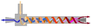
Cryogenic cooling with CO2 utilizes a special case of phase change. Because of its chemical properties, it has no liquid state below 75 psi.  It is said to have a triple point instead, where it can simultaneously exist in all three states, liquid, gas, and solid.  Most elements or chemical compounds have a triple point at some combination of pressure and temperature ( for example water has a triple point at .088 atmospheres and 0.01 Degrees C.)  For CO2 the triple point happens in the range releasing to atmosphere CO2 of normal tank temperatures and pressures.  What this means for cooling purposes is that when liquid CO2 is precisely introduced to the system and the pressure is dropped dramatically such as at the nozzle of a spray gun or cooling injector tube on a temperature chamber or thermal platform (cold plate), the liquid quickly turns to dry ice snow, solid-state CO2. As the dry ice warms up, the resulting phase change is the direct change from solid to gas, called sublimation.  There is a great release of the latent heat as the CO2sublimates.

Because CO2 readily goes into the solid state for cooling processes, it can sometimes be troublesome if there is some problem that might cause too much coolant to be expanded into a solid at once and cause blockage of the cooling system.  It is very important to design CO2 supply and control systems so that the cross-section of the plumbing line never (expands and subsequently) restricts.  This will invariably result in dry ice blockage.

Due to the lower costs to capture and compress CO2, it is generally commercially cheaper and for that reason can be a preferable coolant. If your cooling requirements are not as extreme (above -50C), CO2 can be a better choice. A properly designed and maintained system will not suffer blockages due to the sudden solidification of liquid CO2.

High pressure (900 psi) CO2 is generally a little less efficient due to the lower heat of vaporization but it can be a better choice when usage is intermittent as it stores indefinitely at room temperature. Low-pressure CO2(~300 psi)  stored in vacuum insulated bottles is often more cost-efficient than LN2. Low-pressure CO2 will store somewhat longer than LN2 because it is stored at about -18C inside the tank as opposed to -190C. By comparison, LN2 can go colder and has greater heat removing capability below -60C, CO2 can be cheaper in larger-scale usage due to its slightly lower volume cost and slightly longer storage times. A couple of further advantages to CO2 cooling is that since it is not nearly as cold upon liquid delivery there, is less loss and consumption delay due to vaporization in the hose.  With less vaporization in the hose, delivery time is more predictable upon startup and after longer pauses in usage.

Click for Free Technical Consultation or call 888.712.2228

What is High Performance Thermal Testing?

What is High Performance Thermal Testing?

I am sure there are quite a few different answers to that question depending on what you are trying to accomplish.

What is your idea of a high-performance thermal test?

Here is my Top Ten List

Temperature Accuracy: For thermal environmental stimulation or temperature cycling, either from an existing requirement or from developing a deeper understanding of the thermal properties of your system, you need to know that your readings and assumptions are correct to make a meaningful test. Good calibration and multiple sensing points help to better understand what you are working with and the best methods for screening your electronic device under test.

Speed: For good or bad, economics drives things and usually the quicker appropriate testing can be done the better.  Increasing throughput is good within the limits that the device can withstand is the goal.

Low Initial and Ongoing Cost: Accurately calculating both initial and ongoing costs can seem foreboding but often can be determined with reasonable accuracy and minimal assumptions. A surprising array of variables are in play however, often some good estimates can be made. Expendable coolant cost and faster test times versus electricity plus the higher maintenance of a refrigeration compressor can be estimated.

Appropriate Automation and Process Verifications as required: A system that automates tests and provides convenient verification by the user, USB removable memory log, or remote communication makes testing more productive.

The Temperature Chamber or Platform is a good fit for the product: Clearly, some products are best tested on a thermal platform (cold plate) and some better in a temperature chamber.  The appropriate size of the chamber can increase speed accuracy and otherwise optimize the process. If the product is suitable for testing on a thermal platform, that often will provide the optimal results.

Ease of Use: Portability / Convenience of Operation: In some cases portability, co-location, or benchtop operation of thermal test gear can provide a significant efficiency advantage.

Special Utilities / Services required: Electrical Service, LN2 / Liquid CO2, ventilation: Any special services required are extra costs, some are one-time and some are ongoing that play into the total cost/performance equation.

Lab Space Required: Lab space is a valuable commodity, thermal testing gear that uses less space is better.

Reliability / Support: Clearly nobody wants to sit around with broken equipment when there is testing that needs to be done, reliable and easily serviced equipment is a must.

Safety: I needed 10 items to round out the list so it’s always a good idea to keep safety in mind.  With cash being tight, many people choose to modify/repurpose or push older worn-out systems back into service, we can’t ever forget safety so if repurposing always think through and test for safe operation with a few unexpected circumstances before calling it good.

What does high-performance temperature testing mean to you?

I am sure many different things to different people.

Let me know what it means to you.

Email Questions & Comments

Thermal Testing Equipment: Maximizing Value

Thermal Testing Equipment: Maximizing Value


In the world of Test and Measurement, there are numerous options for your temperature testing equipment. They can have a significant impact on costs, upfront and ongoing as well as ease and quality of results. For maximum value from your equipment, it is helpful to better understand the methods and choices available to you.

With temperature testing equipment, there is more than one choice for how to accomplish heating and cooling. In most cases, resistance heating is the heating method of choice, thus the primary basis of the decision becomes a discussion of cooling options. For cooling methods, there are several choices and the costs vary dramatically. Finding the best available value for that equipment often depends on determining the specific requirements for your unique application. Here are several factors for your consideration:

Methods of Cooling 

Mechanical Refrigeration, – Closed-loop compressor-based systems.

Expendable Coolants – Cryogenics i.e. Liquid Nitrogen (L-N2) or Liquid Carbon Dioxide (L-CO2).

Thermoelectric Cooling – Peltier Chiller Systems.

Recirculating Fluid Chiller Systems and Liquid Baths.

For more details on the cooling method trade-offs visit our  blog post:

Methods of Heat Transfer 

Convection –

Temperature Chambers/recirculating air or Forced.

Air Systems, non-recirculating air such as a thermal airstream system.

Conduction –  Thermal Platforms.

See our whitepaper on Conduction v. Convection for Thermal testing.

When choosing a chamber to meet your needs, good airflow is essential, the air ramp rate of an empty chamber will seem much faster until you put your load inside with a chamber that has low airflow.

As we learn in Physics class, conduction is the most effective process for heat transfer but it is not always possible due to the shape and geometry of the device to test.

In many cases, it comes down to choosing between a chamber or a thermal platform with the shape of the device under test dictating the choice for a chamber. Airstream systems are often a good choice for one at a time component testing but often impractical for production situations where multiple cumbersome systems or queuing of the parts to be tested would be required.

A Summary of the Main Systems Used for Thermal Testing


For versatility, standard chambers are very popular and meet the needs of a lot of testing purposes.  Often they are more price competitive due to the larger scale market. Again if performance is important pay attention to airflow rates and ramping rates WITH LOAD.  Higher performance often means more power, large expensive, noisy compressor systems that require maintenance, or Expendable Cryogenic coolants like L-N2. Chambers provide performance regardless of the shape of the device under test, are typically slower transitioning and settling, and require more lab space.

Forced air or airstream systems are very good for spot cooling applications, they are bulkier than thermal platforms but also less sensitive to the shape of the device.  They are typically more expensive and require more power and more maintenance.  They can provide fast accurate temperature control with better accessibility to the device than chambers.

Platforms control temperature by conductive heat transfer and thus are inherently faster however are restricted to devices that have a flat conductive surface or can be fixtured to work on a platform.  They are generally less expensive to buy and operate.  Platforms provide fast-cycling time,  require little laboratory real estate, and offer very good accessibility to test objects.

The flexibility and ease of use of the temperature controller and the ability to readily produce recorded test records in an automated way is also important consideration for thermal testing value.

As you see, there are several aspects to consider when choosing thermal testing equipment.

If you would like our trained consultants to talk with you and answer any additional questions you may have.

More to follow on methods and value of combined conduction and convection heat transfer.

Example of Ten Production Thermal Platform Systems requiring far less lab space and power than other types of thermal test systems.

Expeditious Thermal Testing Visited Anew

Expeditious Thermal Testing Visited Anew


There are many ways to do thermal testing right, many ways to do thermal testing wrong, and many ways to do a mediocre job with it.

Here are several aspects of thermal testing to consider:

  1. Actually performing a test that is adequate to accomplish the need, requirement, and intent of the testing plan.
  2. The efficiency of time and labor used for the test.
  3. The efficiency of facilities requirements.
  4. Reliability and repeatability of testing.

Heat Transfer by conduction using thermal platforms/hot-cold plates are known to be faster and more efficient but due to complex shapes of many parts not always practical.  Heat transfer by convection using temperature chambers that have respectable airflow allows heat to be transferred efficiently to and from irregularly shaped devices. With modern control and monitoring methods, it is now a lot easier to verify that temperatures at specific locations are actually being achieved and held for the specified durations.

The combination of convection and conduction holds several promises of improving the whole thermal testing game.  Easily accessible benchtop thermal testing that combines the benefits of convection and conduction allows better performance and accessibility while the unit is under test which is often important for probing or other R & D operations. A small benchtop unit saves time with technicians no longer needing to stop, get up and walk over to a temperature chamber. Smaller batches also mean less waiting in queue for the start of thermal testing. A test stand with a small footprint consumes less precious lab space and uses less power than conventional chambers. Simple L-N2 / L-CO2 cooled systems are quite fast, economical, have very low maintenance requirements.

Modern controllers are easily automated with Ethernet, GPIB, FTP, email, logging, web server, network printing and texting capability will keep test operators informed of testing status and expedite accurate reporting of test results.

TotalTemp Technologies offers advanced thermal testing systems, off the shelf and custom engineered systems. Call today to talk with experienced representatives that help plan the best solution for your testing requirements.

Check out our new product combining the advantages of thermal testing with both convection and conduction: https://www.totaltemptech.com/totaltemp-hybrid-benchtop-chamber/

Replacing programmable instruments, keeping software compatibility in an automated test

Replacing programmable instruments, keeping software compatibility in an automated test

When an instrument eventually goes obsolete or for any other reason a new instrument is put in place of one that is already a part of an automated test system, some programming work will follow to make the transition complete.  Even if the instruments are supposed to be software compatible, there are often minor details to tend.  The good news is that it is usually not that difficult or involved. Of course, exceptions can be noted but usually, it is not as big of a project as some anticipate.

We have had programmable test equipment with us now for well over fifty years and a lot has been written about making instruments easier to program. Indeed great progress has been made and hopefully, at some point in the future, and inclusive common language such as SCPI (Standard Commands for Programmable Instruments) for all test gear could be fully in place, functional, and accepted by all manufacturers.  This type of command structure may be more deterministic with some instruments than others, however at this point in time it seems to remain a fact that different programmable instruments evolved over different courses of development, in particular, temperature chambers, so I believe there will ultimately remain a few little details one should be prepared to attend to whenever swapping these instruments.

The following is an example of the methodology used to transition from communicating a Sigma temperature controller to Tidal Engineering’s Synergy line of temperature controllers used by TotalTemp Technologies. Outlined are the comparisons of the two different command strings and expected responses.

Without getting into software specifics such as conditional code and so on – This is how we make it work without a lot of difficulties.  (App note produced by Tidal Engineering (www.tidaleng.com)

Synergy Controller Application note 111

Please share your experiences with swapping instruments and compatibility between programmable instruments that perform the same function.

Thermal Testing with Conduction? – Double Check your true area of Contact!

Thermal Testing with Conduction? – Double Check your true area of Contact!


To achieve the benefits of thermal testing with conduction, thermal platforms also known as Hot/Cold Plates are used to force devices to specific temperatures.  While Thermal Platforms may not work for every application, where they do, they offer a distinct advantage in speed, accessibility, efficiency, and production throughput.  Items with irregular surfaces or even vials or beakers can often be fixtured to work well on a platform and allow for much better cost efficiency than found with temperature chambers.

For heat transfer reasons, the best physical configuration for the Device Under Test (DUT) is one with a flat thermally conductive surface and low profile. Think something shaped like a book.  However, the term “flat” can be critical when it comes to proper, efficient thermal conduction testing. Typically, the surface of most thermal platforms is Blanchard or disc ground to within 0.005”.  Likewise, the bottom surface of the DUT must be very flat too for good heat transfer.

If the bottom of the DUT had just the slightest bow to it, even only a few thousandths of an inch, sometimes no appropriate amount of pressure can accomplish full surface to surface contact. The bottom of the DUT could easily be missing a large area of contact, occasionally a surprising amount of the surface is not in contact at all.   You can often get a good visualization of the surface flatness by placing a flat straightedge against the bottom of your device.  Additionally, microscopic surface variations are very important.  The following, on the left, is a microscopic picture (200x) of an aluminum surface that would look perfectly flat to the casual viewer.  You can see a very small percentage of the surface would actually be available for contact. On the left, a Blanchard ground surface maintains much better overall flatness at the microscopic level.

Anodized Wrote aluminum on Left, Cast Blanchard Ground plate on Right

Losing a large percentage of contact between the DUT and platform surface can be hugely wasteful of resources and you may not be performing the test you think. it can definitely affect production throughput as consideration for improving thermal performance. Let’s talk about some ways to resolve and/or improve this issue:

Thermal Grease – The heat transfer can be improved by applying thermal grease between the surfaces. Especially when the surfaces cannot be made as flat as desired.  Much has been written, some of it contradictory within the realm of high-performance CPUs regarding the best thermal grease.  If you can achieve flat surfaces little or no grease will be required.

A few things to remember about thermal grease:

  1. Grease never conducts as well as metal but is always better than air.
  2. Usually, less is better.
  3. Grease is messy and often not reusable.
  4. There are a lot of different greases, for practical purposes, standard white silicone grease such as Wakefield 120 works about as well as any.
  5. If you can’t keep the grease clean, start over.  LIGHT circular sanding with scotchbrite (the abrasive on kitchen sponges) or similar will smooth and clean the surface best. Wipe with denatured alcohol if necessary to make sure surfaces are clean and particle-free.
  6. Your results may vary depending on the application.

It is important to have flatness so good that you cannot detect any gaps between surfaces. This becomes more challenging as surfaces become larger.  When you are unable to improve the flatness of your DUT, or force good surface to surface contact with adequate pressure, then using thermal grease to fill the voids can be very helpful. That is all thermal grease is really good for, replacing the insulating factor of air, with something that is somewhat less insulating and more conductive. Thermal pads are an alternative to grease, they transfer heat less effectively but are easier to use and less messy than grease.

Fastening Down the DUT – You have the option of ordering custom hole patterns in the plate surface to match your DUT screw-down pattern. Even the size of the hole and thread count can be called out to meet your specific application. This is a very common and probably the best way to secure the DUT to the plate. It is best to order the hole pattern at the same time as the platform so they are machined into the plate surface prior to anodizing, and assembly. In some cases, these holes can be drilled after purchase, but definitely consult the plate manufacturer first, to ensure you have adequate clearance. Drilling too deep into a heater or cooling channel can be an expensive mistake.

Clamping the DUT down to the Plate Surface – This can be a fairly efficient way to improve DUT to plate surface contact. In some cases depending on the size of the DUT, several clamps can be used.  Typically, the clamps are attached to the plate surface with a threaded post. If your manufacturer does not provide threaded holes in the plate surface as a standard feature, you will likely want to specify that option when purchasing.

Clamp Set on a Thermal Platform.  Threaded mounting holes come as a standard feature.

Lastly, some users rely on the weight of the DUT itself to provide adequate contact. Some will add weights to the DUT, care must be taken so that the added mass does not cause damage or add more of a thermally conductive load to the test. Adding weights would be the least desirable method for attempting good DUT to plate surface contact.

When looking to purchase new, it is highly advisable that you speak to the Sales Engineer about the methods and options available from them for securing the DUT to their thermal platform.

Thermal Testing Limit Safety

Thermal Testing Limit Safety

Temperature Range Safety

Temperature chambers and hot/cold plates are invaluable tools for environmental simulation thermal testing.

Inherent in their performance capabilities are some risks, primarily the possibility of exposing items (and people) to extreme temperatures resulting in damage, injury, or combustion. When testing it is obviously important to make sure devices or samples to be tested are not exposed to temperatures outside the intended temperature range.  In cases such as flight or space hardware the cost of disqualified hardware, even if it was only briefly exposed to excessive cooling alone can be enormous.

Several approaches singularly applied or redundantly will reduce the risk of losses.

These systems are known by several names: Thermal Range safety, System Failsafe, Limit Controller, or Latching Thermostat, to name a few.  Some of these systems can be communicated with by automated test systems.

To start with, most modern temperature chambers or thermal platforms offer several levels of protection starting with the temperature controller.  Temperature controllers typically are designed to prevent users from requesting temperatures that would damage the system itself if not strictly the items under test.  Often there are locked limits that are set at the factory to protect the test equipment and additional user limits that can be set to prevent accidental damage to devices under test.  Beyond that many controllers will also go into an ALARM shutdown mode if the attached sensor reads outside the preset range.

The first way that requires thought of additional protection is for excessive or runaway heating. For example, if the output device that switches heaters sticks on, a controller alarm condition may not effectively stop runaway heating. Most systems include some sort of an additional latching thermostat that will shut down any heating when a limit temperature has been exceeded due to system problems, component failure, human error, or other causes.  The latching function keeps the heat from cycling back on if no human intervention in the form of a reset, power down, or other status confirmation has occurred.


Failsafe Limit controller circled                Redundant L-N2 valve assembly

Systems that are air-cooled, or cooled with single-stage refrigeration are less likely to cause damage from runaway cooling conditions but often times protection from excessively cold temperatures are required as well.  If cooling is performed using L-CO2, multiple stage refrigeration, or especially if L-N2 then cooling limit protection is also highly recommended due to the extreme temperatures possible.  Many limit protection systems can respond to both high and low limits in one unit. Protecting from extremely cold temperatures when cooling with L-N2 will often require a little additional planning.  Unlike protecting from high temperatures, removing power from the system for a cold temperature runaway event is not as likely to provide full protection from cold.  The most common example of this would be contamination causing the plunger in the L-N2 valve to stick open.  Killing the power will not likely release the plunger.  For these cases, the addition of a redundant L-N2 valve wired to the limit controller is a good choice, especially if there is a possibility of unattended or overnight testing.  The redundant valve stays energized so it is not receiving the same operational wear and tear as the control valve.

Following this thought, it is also good to look at the possibility of unintended heating due to an active load in the system or even high-velocity chamber blowers which can produce unexpectedly high temperatures. (well over 100C in the chamber is possible due to air friction alone, without the heat turned on!)  In these cases, it is good to ensure that functionality is in place to shut off possible active heat load sources in the chamber including chamber high-velocity blowers.  Keep in mind it works both ways. Blowers running after a shutdown will help cool self-heating products but also cause more heating due to air friction.

It is always a good idea to plan ahead when specifying new thermal test equipment. Existing chambers that don’t already have enough levels of built-in safety can often be retrofitted with integrated safety limit controllers that employ independent temperature sensing and internal system shut down capabilities.  If the addition of internal retrofit limit controls is not feasible, an external limit controller system can be employed to provide required levels of safety.  TotalTemp Technologies offers a variety of safety controls for hot/cold plates or chambers.


Selecting the Right L-N2 Coolant Delivery Hose

Selecting the Right L-N2 Coolant Delivery Hose

Expendable cryogenic liquids (L-N2 or L-CO2) deliver quick, accurate, economical, and precise cooling for testing electronic systems and components. Using the right hose will help make sure you get the best speed reliability and long-term economy out of your coolant.

.

Vacuum Jacketed Delivery Hose

Liquid Nitrogen is cold!   Approximately -180°C and it delivers the precise, powerful cooling capability for thermal platforms or other thermal testing equipment.  However, due to the extremely low temperature, losses due to poorly insulated hoses can result.  When specifying an LN2 delivery hose, use a vacuum jacketed hose and the shortest comfortable length possible to minimize losses.

Liquid from the tank vaporizes immediately when it hits the warm hose and wastes time and cooling potential.

A good quality vacuum jacketed hose provides benefits in several ways

1)  Vacuum insulation, like that used for the tank is the best insulation possible to reduce losses due to the extreme temperature difference between the coolant temperature and the ambient temperature hose.

2)  Unpredictable delays are often experienced while coolant is flowing and waiting for the hose to cool down.  More predictable cooling rates of a good supply of coolant will make it easier for control algorithms to function resulting in less delay or instability of temperature.

3)  Pressure can increase several hundred times as a liquid warms and tries to vaporize in a hose that is shut off at both ends.  Quality vacuum jacketed hoses will have a built-in pressure relief valve that relieves excessive pressure that could result in unsafe pressures if a hose is shut off at both ends or from other overpressure situations.

4)  Most factories have rules about the safety hazards of water on the floor.  Less condensation on L-N2 lines is safer too. With poorly insulated non-vacuum jacketed hoses, extremely cold or long-term testing can result in frost or condensation on the L-N2 plumbing which usually ends up like water on the floor.

If usage is short-term or very intermittent, an armored, non-vacuum jacketed hose may be called for as a cost-saving measure but in most cases, the above benefits of a good quality vacuum jacketed hose are worth the extra cost.

While on the subject: a few points to know about vacuum jacketed hoses

Delays due to vaporization in the hose are worse at lower L-N2 pressures.

Be gentle, dropping or otherwise slamming a vacuum jacketed hose can result in a tiny amount or complete loss of vacuum.

If a hose shows signs of lost vacuum (sweating) –

Sweating Vacuum Jacketed hose shows loss of vacuum

it can usually be re-evacuated to make it perform properly again.

Factory tools and equipment are needed to re-evaluate and test the vacuum seal

The Pressure Relief Valve (PRV) is there for the L-N2 safety of people in the lab, don’t alter or remove it.

Pressure Relief valve with Candycane Riser

The pressure relief valve works best when the outlet is pointing generally downward.  This reduces the chances that the valve may weep, leak or stick open if it should become icy. A candy cane riser is an optional J-shaped pipe nipple that allows the proper orientation of the PRV.

When a tank will be used later, it is generally better to leave the liquid valve at the tank ON, that way the warming, vaporizing, and resulting pressure increase will return to the tank and not unnecessarily cause the Pressure Relief Valve to vent.  The PRV is there to help improve safety but it is best to not rely on it. Pressure generally will climb over 400 psi. before the valve opens. The solenoid valve on a typical hot-cold plate or chamber will in most cases not open properly at this pressure.

CONTACT US

Please reach out with any questions you have regarding LN-2 delivery hoses or hot/cold plates, temperature chambers, or other thermal test equipment!

Spot Cooling with Vortex Tubes – a Viable Option

Spot Cooling with Vortex Tubes – a Viable Option

When using temperature chambers or thermal platforms to do thermal testing, the heating of devices tends to be more or less straightforward. Generally, electrical resistance heating, be it conductive or convection (or even radiant) is the best, cheapest, and most easily controllable method.

However when it comes to cooling, there are a few more options, the primary ones being mechanical refrigeration, expendable cryogenic gas such as L-CO2 or L-N2,  Peltier (thermoelectric), or – for some, generally smaller applications, vortex tubes are also an option.

Not to be confused with ordinary Venturi tubes, the official name of the device is the Ranque-Hilsch vortex tube.  These clever devices are able to provide a surprising amount of refrigeration capacity from compressed air alone.  They are best for small lower-cost spot cooling applications since they are a lot simpler and easier to maintain than refrigeration systems. They are somewhat less efficient at cooling than a typical refrigeration system.  Efficiency is comparable to Peltier cooling.

The summary description of the operation from Wikipedia:  Pressurized gas is injected tangentially into a swirl chamber and accelerated to a high rate of rotation.  Due to the conical nozzle at the end of the tube, only the outer shell of the compressed gas is allowed to escape at that end.  The remainder of the gas is forced to return in an inner vortex of reduced diameter within the outer vortex…

The main physical phenomenon of the vortex tube is the temperature separation between the cold vortex core and the warm vortex periphery.  The vortex tube is essentially a rotors turboexpander.   It consists of a rotor’s radial inflow turbine (cold end, in the center) and a rotors centrifugal compressor (hot end on the periphery).  The work output of the turbine is converted into heat by the compressor at the hot end.  This explanation of the heating/chilling effect stems from the law of energy conservation.

For the practical application, a small vortex tube with 100 psi room temperature air and an available flow rate of 5-10 SCFM can produce a temperature drop of 50 degrees C and removal of 2800 BTU/Hr., or around 800 Watts.

A couple of realistic concepts and limitations to using vortex tubes:

1.  Air source must be clean and of good capacity per above, this will enable long life with little or no maintenance

2.  Use of proper muffler is suggested to minimize exhaust noise

3.  Small active loads on cold plates or chambers will work well with vortex tubes

4.  Systems can be optimized for more capacity or more temperature differential.

5.  Properly integrated into a hot-cold plate or small chamber, a vortex tube chiller may be the best choice for small low capacity cooling needs.

TotalTemp Technology is happy to talk with you about your thermal testing requirements.

Feel Free to reach out with your questions.

RTD’s v. Thermocouples, which is best?

RTD’s v. Thermocouples, which is best?

RTDs v. Thermocouples

The question is often asked, “what is the best temperature sensor for my temperature testing or environmental testing application?”

The answers can vary a lot but the two main leaders of the pack are RTDs (Resistance Temperature Detector) followed by Thermocouples.

If you are looking for the short answer of which is best, it is RTD’s but here is a little more to the story

The primary reasons RTD are best:

Better long-term stability, more linear response, More gain- that is more signal change for a given temperature change, also they have easier to manage lead wire connections.

So why would someone choose a Thermocouple over an RTD?

Arguments in favor of Thermocouples:

The number one reason – Thermocouples are cheaper.  Market demands often dictate cheaper.

Thermocouples generally hold up better in environments of severe vibration or thermal shock.

They typically are better for point sensing instead of sensing a larger area or air temperature.

Stepping back a little: There are more tradeoffs, but those are the main considerations. To be fair, there are other viable temperature sensors for many applications but just a short history lesson first. German Physicist Thomas Johann Seebeck first discovered in 1821 that any junction of dissimilar metals will produce an electric potential related to temperature.  Thus the name for a device that senses temperature by the coupling of two metals.  The result was the first electronic temperature sensing device and it could be designed to work without any external power source. A couple of issues about how this sensor works are: 1) The carefully controlled types of metals in the sensor used have to be continued all the way to the instrument that is measuring the temperature. 2) The instrument itself requires an additional thermocouple to be used as a fixed reference.  Since the temperature of the fixed reference usually changes, often an additional RTD or bandgap sensor is used to compensate for the thermocouple calibration.

In 1871 Sir William Siemens discovered the Resistance Temperature Detector or RTD.  He found that Platinum wire and other materials have a well-defined relationship between temperature and the electrical resistance of the material.  The relationship between temperature and ohms is much more linear and easier to work with than the relationship between volts and temperature with thermocouples.

Thermistors are simply a specific type of RTD, often made with a polymer or cheaper materials than Platinum.  They typically have a narrower temperature range and have less long-term accuracy. Also as a side note, Thermistors most often but not always have a Negative Temperature Coefficient (NTC), meaning that they have less resistance as temperatures get higher.  This feature makes them handy for several special compensation applications, for example canceling out other factors that increase with temperature.

The Bandgap (transistor) Temperature Sensor is one other significant, modern temperature sensor.  This device makes use of the known effect that the forward Base to Emitter voltage of any transistor is directly and predictably affected by temperature.  These devices although rarely used in applications such as temperature chambers are popular because they are inexpensive and can be easily integrated into other silicon circuits making internal component temperature sensing very simple and affordable.  Their usability is primarily limited to the range of -40C to +200C.

RTDs are widely accepted as the preferred temperature sensor for long-term repeatability.  It is my position that they will continue to prevail as “the best quality sensor” however I do hear some interesting reports that there have been recent improvements to the technology of making and reading thermocouples.  I think the jury is still out but I would be interested to hear what experiences others have had with a so-called new generation of thermocouples and available accompanying 24-bit A/D sensing circuits.

As a final note, there are several distinctions between types of thermocouples and likewise different types of RTDs.  The thermocouple type must match the type the instrument is configured to read.  In the same manner, the RTD must match the curve (Typically DIN curve) the controller is configured for.  Additionally, the RTD has a base resistance value that must match controller configuration (typically 100 ohms at 0C)

If you want to know more, just ask.

TotalTemp Technologies offers a selection of 100 and 500 ohm RTDs and thermocouples for thermal platforms and other applications.

Our experienced team can provide assistance with your temperature sensing, hot/cold plate controlling, and thermal testing needs.