A thermal vacuum chamber (TVC or TVAC) is a specialized type of test equipment that simulates the environmental conditions of space. It is primarily used to evaluate the performance, durability, and reliability of spacecraft components, satellites, and other equipment intended for use in space extreme temperatures environments.
Thermal vacuum chambers play a vital role in space exploration and technology development. By providing a controlled simulation of the space environment, they help engineers identify and address potential failures before deployment. This not only ensures mission success but also enhances the safety and longevity of space equipment.
Whether launching satellites, building rovers, or testing the resilience of new materials, thermal vacuum chambers are indispensable tools in the pursuit of space innovation.
Key Characteristics of a Thermal Vacuum Chamber
1. Vacuum Simulation
By replicating the near-vacuum of space, this chamber eliminates atmospheric pressure and convective heat transfer, mirroring conditions where a pressure of 1 x 10⁻⁶ torr corresponds to a staggering altitude of about 650,000 feet (198 kilometers). The extreme temperatures encountered at such altitudes, driven by the thermosphere’s absorption of intense solar radiation, highlight why research in this environment is paramount for guaranteeing the safety of future space missions.
2. Thermal Cycling
TVACs can simulate extreme temperature fluctuations, mimicking the conditions experienced in space when a spacecraft transitions between the sunlit and shadowed sides of orbit. These temperature shifts can range from extreme heat to freezing cold which can pose material failure and/or significant performance impact if it is not designed and tested properly. For instance, the temperatures around the ISS (International Space Station) can range from around 250°F (121°C) in direct sunlight to -250°F (-157°C) in the shade.
3. Controlled Environment
The vacuum chamber is equipped with advanced systems to monitor vacuum level. Thermal platform temperatures are controlled by our Award-Winning Synergy Controller ensuring precise control for environmental testing conditions.
Applications for a Thermal Vacuum Chamber
Aerospace Engineering
Thermal vacuum chambers are critical for testing satellites, spacecraft, and other aerospace equipment, ensuring they perform optimally in the vacuum and temperature extremes of space.
Material Testing
Engineers use these chambers to evaluate how materials react to prolonged exposure to vacuum conditions and thermal cycling.
Electronics Testing
Advanced electronics, sensors, and communication devices are tested in a TVAC to ensure they can function reliably in space.
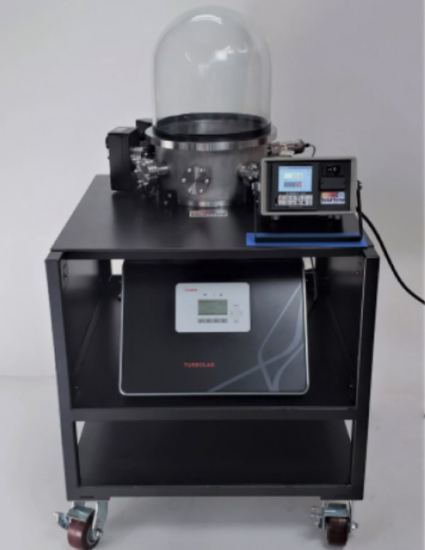
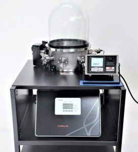
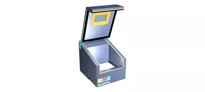
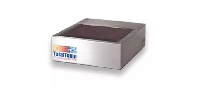
The Next Generation TotalTemp Thermal Vacuum (TVAC) Chamber
Compact and portable, the TotalTemp TVAC Chamber is designed for fast and efficient testing of small devices using advanced conductive heat transfer technology.
Figure 1: VmSD49-N
Specifications:
Temperature Range: -70°C to +175°C │ Vacuum Capability: Up to 1×10⁻⁶ Torr
VmSD49-N: Offers a 6.5″ x 7.5″ usable surface area (49 sq. in / 315 sq. cm)
VmSD144-N: Features a 12″ x 12″ usable surface area (144 sq. in / 929 sq. cm)
Primary Features & Benefits:
Custom Sizes: Tailored solutions available to meet your needs
Simulation Flexibility: High-altitude or space conditions up to 1 x 10⁻⁶ Torr
Precise Temperature Control: Range of -70°C to +175°C
Coolant System: Utilizes Liquid Nitrogen for cooling
Heating Technology: Embedded resistance heaters for rapid uniform heating
The TotalTemp TVAC Chamber offers unparalleled precision for applications requiring reliable vacuum and thermal testing in a portable solution.
The TotalTemp TVAC Chamber offers highly efficient advantages for conductive heat transfer in high vacuum environments. With the increasing deployment of new hardware in space, where servicing is nearly impossible, thermal vacuum testing has become a critical component in evaluating high-altitude and satellite equipment.
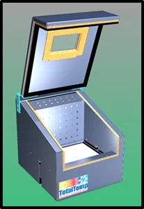
Our solutions are affordable and customizable to meet your specific needs. Perform simultaneously high vacuum and thermal testing without the need to rent time at an external test lab. We provide thermal platforms designed to fit your vacuum chamber, as well as complete turnkey systems. The platform shown inside the bell jar measures 6.5” x 7.5”, with other sizes and various bell jars also available
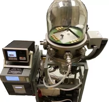
Figure 2: Early Version of the VmSD49-N
TVAC for Environmental Aerospace Testing
TotalTemp’s Thermal vacuum chambers (TVAC) play a critical role in aerospace environmental testing by identifying potential issues caused by drastic temperature changes and atmospheric pressure variations, conditions commonly experienced in space. Since space-bound equipment carries high stakes due to the cost of launches and the catastrophic consequences of failure, ensuring reliability through rigorous testing is essential. Furthermore, repairs or adjustments in space are both difficult and incredibly expensive, making pre-launch testing indispensable.
A significant distinction between testing for space and land systems lies in heat transfer. On Earth, air allows for heat transfer by convection, but space presents an entirely different challenge due to the absence of air. This requires testing methods that mimic the heat transfer mechanisms unique to the vacuum of space, where thermal performance heavily depends on radiation and conduction alone.
Outgassing, a phenomenon where materials release trapped gases in the vacuum environment of space, is another crucial consideration. While it may not be a significant problem on Earth, outgassing can severely compromise the function of equipment in space, requiring careful material selection and planning.
To ensure components perform effectively in the harsh conditions of space or low Earth orbit, they are tested under simulated space environments. Standardized testing protocols maximize reliability and prepare equipment for real missions.
Commonly used standards include:
MIL-STD-202
MIL-STD-810
RTCA/DO-160
ISO/AWI 15104, ECSS-Q-ST-70-02C
SMC-C-016
While larger thermal vacuum chambers are often used for full-scale system testing, they are typically expensive and accessible only to larger institutions. Smaller, portable thermal vacuum chambers offer a cost-effective and flexible alternative for testing components and subsystems before integration into larger systems.
Portable TVAC chambers also have the advantage of faster vacuum levels and temperature achievement compared to larger chambers. This leads to significant benefits in efficiency, convenience, and accessibility, making these systems an excellent investment for smaller organizations or teams requiring frequent testing capabilities on demand.
With advancements in thermal vacuum technology and adherence to stringent testing standards, aerospace professionals can ensure their equipment is ready to perform reliably in space’s extreme and uncompromising environment.
Popular benefits and advantages of Portable Thermal Vacuum Chambers:
Cost Savings: Affordable models provide high functionality at a fraction of the price of fixed, larger chambers.
Mobility: Easy to move between labs or departments for flexible usage.
Space-Efficient: Ideal for smaller labs without dedicated large-scale testing areas.
Time-Efficient: Pull downtimes for achieving vacuum are typically minutes instead of hours when using a small portable system.
Offers thermal platforms & temperature chambers designed for accurate and expedient testing. Our industry-leading platforms and temperature chambers are matched by our superior customer service.
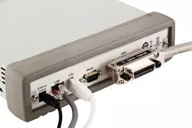
Controlling Instruments with GPIB, Ethernet, USB…or What is Next?
Which Bus is Best for Instrument Control?
Selecting the right computer bus for your test equipment is a little bit of a moving target but fortunately is moved fairly slowly and moving in the direction of better.
RS-232 – originating back in the early ’60s, RS-232 was developed as a standard for serial digital communication. Connecting computers to other computers or remote instrument communication with a minimum number of wires was the primary use. For a while, it became the most popular standard for sending data computer to computer or between instruments and computers, especially over phone lines with the use of a modem to couple the signal long-distance over existing phone lines.
By current standards, RS-232 is limited by the low transmission speeds, large connectors, and relatively large voltage swings required. For instrumentation purposes it is limited as well by the fact that a given RS-232 link is single-ended, that is one RS-232 port would be required for each instrument to be communicated with.
GPIB – In the late ’60s seeing the need for something better, Hewlett Packard developed the HP-IB computer bus (Hewlett Packard Interface Bus). which is now more frequently referred to as GPIB (General Purpose Interface Bus) or IEEE-488, the name of the formalized standard for the interface. GPIB boasted good speed due to the 8-bit parallel nature of the bus, meaning that 8 bits of synchronized data are transmitted at each interval of communication, theoretically making it faster. One other great advantage of the GPIB over RS-232 communication is that multiple instruments could share the same bus or network, thus reducing the number of ports required on a host computer. The downsides of this interface were that it was often troublesome to set up and hardware, connections, and cabling were all very bulky and expensive. GPIB cables are often difficult to route through equipment racks and have limited bend radius and maximum allowable run from device to device.
Ethernet – Conceived in the ’70s began its development at Xerox as an efficient computer to computer networking technology and eventually became refined and standardized in the early 80’s to be much of what we know today, displacing competing for network technologies such as Token Ring and Token Bus. Originally, the coaxial cable form is known as 10BASE-5 then 10BASE-2 gave way to the form we know today as 10BASE-T, denoting twisted pairs in lieu of the more troublesome and expensive coaxial form. This shift to twisted pair gave the Ethernet a great boost in reliability, cost and speed, and eventually market share.
Ethernet, because it was originally developed more for computer communication had in some cases been considered less suitable for instrument communication due to the lack of some instrumentation features such as group trigger, designed to allow several instruments to take a measurement at the same instant. Further, Ethernet had been considered less deterministic in general, meaning that exact timing and synchronization of events is less well-controlled even though it is generally much faster.
In 2005, LXI, or LAN eXtensions for Instrumentation standard was Introduced. Although not all LAN-based instruments need or support this extra functionality it effectively resolves the indeterminate conditions of the bus by providing timing and trigger functions based on the IEEE1588 standard. Additionally, HiSLIP (High-Speed LAN Instrument Protocol) enhances the LAN’s capabilities to work well with instruments.
USB – Universal Serial Bus, was developed in the mid-’90s as the next step in communication for the PC beyond RS-232. Primarily for hooking peripheral devices, providing more standardization with plug and play, faster communication plus sharing of a port between several devices(often with a simple internal or external hub). As an added bonus, the USB can often provide the needed power to operate peripheral devices. With regard to instrumentation systems, USB has developed some following as a low cost, easy to implement communication method for measurement. At least partially due to the fact that all modern computers now have USB ports built-in. Several major manufacturers of test equipment now offer equipment with USB communication capabilities for easy automation projects. The latest iterations of USB with yet higher speed make it a very capable system for many instrumentation needs. The USB specification even has some well-defined Test and Measurement Class (USBTMC) of protocols for instrumentation and emulating GPIB data type transactions.
Still GPIB…While the tide is slowly turning more towards Ethernet at this time, GIPB continues to amaze people with its persistence. While so much in the tech world is very fast to change to newer cheaper and better technology, GPIB remains surprisingly entrenched in the test and measurement arena. With easy-to-implement devices such as National Instruments ENET/100 that can translate from GPIB to Ethernet, it is not very difficult to cope with an existing legacy device that may still be required that only supports GPIB and not Ethernet. It seems to be the belief of most of the Test and Measurement community that in time, Ethernet, often with an isolated network will prevail as the dominant interface between instruments and PCs.
Structured Programming – Structured Programming is a programming paradigm making extensive use of subroutines and block format structures. It follows through to many higher-level languages improving troubleshooting, and maintenance of the software. Emerging back in the ’60s the need to make coding more precise, deterministic, reusable, and verifiable, Structured Programming is now accepted as good practice yet is still resisted by some. Proper use of structured programming facilitates among other things, easy transition from legacy protocols and busses to more current technologies. While there is some value in the “if it is not broke then don’t mess around with it” thought process, inevitably at some point in the future there will be motivation for change in the forward direction. Having structured programming in place that is modular and easily maintainable will enhance any system that is not already doomed to a fixed lifespan. Having seen the changes over the years, it is not likely that the changes in instruments or computer busses will come to a halt soon.
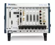
VXI and PXI – Two other bus structures for communication with instruments are of note here as well, PXI and VXI, both of these are substantially instruments without user interfaces, built on the architecture of existing computer bus technology. VXI is a VME computer bus extended for Instrumentation and the PXI is PCI bus extended for Instrumentation. These instruments must live in a host computer or bus expansion chassis. They cannot stand alone like the usual benchtop instruments but rely on the host computer to operate. They are often implemented when instruments are dedicated to a task and are not really required to have front panel controls and displays. There can be notable cost and space savings by the integration with the computer as the sole user interface or control mode. Only a few instruments are really hard to find in PXI or LXI form, Temperature chamber/Thermal platformscontrollers would be one of those hard to find in VXI or PXI form. In this case, Ethernet can easily control the Thermal conditioning system while other instruments still enjoy the benefits of the integrated system.
VISA – Virtual Instrument Software Architecture (a standard under the control of Interchangeable Virtual Instrument or IVI Foundation) is a widely used input/output application programming interface used for facilitating communicating with instruments from a PC The specifications included in The VISA data structures make it far easier to change instruments commands or change communication busses without dismantling the whole structure of existing test software. Most of the larger instrument manufacturers implement the VISA structures in their instruments. Following these protocols produces robust determinant communication that can easily be changed, upgraded, or modified, making life much easier in the event that an instrument or existing bus structure must be replaced or upgraded.
SCPI – (Standard Commands for Programmable instruments), now also under the control of the IVI Foundation, SCPI carries the standardization and interchangeability of instruments concept yet further. If a given instrument is designed to implement the SCPI protocol, as an example, in theory, one brand of programmable voltmeter can be unplugged and another brand of voltmeter plugged in in its place to take the same reading using the same standardized command set. Even another type of instrument, perhaps a scope capable of making a voltage reading might be sent the same commands as the voltmeter and return the reading in the same format. The practical benefits to the user seem great. Many of the more mainstream vendors seem to be on board with this already although not all manufacturers have adopted these standardized commands and syntaxes.
Conclusion – It is hard to predict what might be next, we can only guess what a few of the future candidates might be, WiFi, Advancements in USB3, Bluetooth, Lightning (well scratch that one) … we will see. A number of articles have been written on the subject and although the change has been slower than many have anticipated, the inevitable fade-out of GPIB is approaching. New systems at this time should be designed around LAN-based LXI technology when possible. In some cases where cost savings are more important, USB can be considered a good choice as well. The formal protocol extensions help but bandwidth limit considerations can still apply since a slower instrument can slow down the whole bus and even in some cases the computer’s overall performance. If a more complex and dedicated system is desired and there is no apparent reason for each instrument to have its own display and control knobs, then perhaps VXI or PXI type instruments with their more tightly integrated systems can provide a good advantage in space and cost savings. RS-232 is still in wide use although most computers have skipped that interface in the move to USB The one instrument per bus capability is limiting for most instrument systems. Fortunately USB to RS-232 converters is cheap, easy to implement, and readily available.
Perhaps two reasons people are reluctant to move away from legacy GPIB systems are 1) unstructured, poorly written code that might blow up if altered, 2) the memory of struggles in setting up and troubleshooting the original configuration of GPIB test equipment. My experience is that many of the headaches involved with setting up GPIB systems stay with GPIB systems. That is to say, more modern systems are easier to design, set up and troubleshoot. That nothing could go wrong but things have improved. A lot.
Temperature Testing – Which Cooling Method is best?
Comparison of cooling methods for Environmental Temperature Testing of Electronics
Many electronic components and systems require thermal cycling equipment in manufacturing or the laboratory for system test, burn-in, or design validation.
While improvements in heat pump design allow compressors to heat as well, in most cases resistance heating is the heating method of choice, this is a discussion of cooling options. For cooling methods, there are several choices.
Three primary ways that things are currently being cooled in the lab are:
Mechanical refrigeration i.e. compressor,
Expendable coolants such as LN2 or CO2,
Thermoelectric cooling. Peltier chiller
The following is a brief study of the choice process for deciding which coolant to use. The strengths and weaknesses of the 3 different cooling methods are outlined below:
When choosing the best system for your requirements, there are a few concerns right away that will guide the process
Cooling capacity: Production environments often thrive on productivity with faster performance. How fast do you need to transition? Do you have a physically large, massive or active load? How cold are you going?
Facilities: Do you have expendable coolant readily available? Does the system have to be portable to an area where the coolant is not available or inconvenient? Is ventilation very limited at the point of use? Is the quantity of heat large enough to be concerned about building heat load?
Does the testing run unattended?
Initial cost v. long-term cost study.
Mechanical Refrigeration
Strengths:
The only resource expended is electricity.
Systems are self-contained, just add electricity.
A variety of industry-standard refrigeration systems or custom designs are available.
Weaknesses:
High initial cost, higher yet if cooling below -40 C is required.
Systems are bulky – More difficult to transport, larger capacity systems require special power.
The larger the capacity, the larger the load on HVAC systems or heating of ambient air
Noisy
Relatively slow cooling speed
They are complex systems with more potential issues, leaks, etc.
Expendable Coolants
Strengths:
Economies of speed due to higher cooling capacities.
Storing, supplying, and delivering cryogenic fluids can be expensive or otherwise challenging.
Some risks and increased costs are due to ultra-low temperatures in expendable coolant systems.
Thermoelectric
Strengths:
The Simplest designs are Possible, some systems have no moving parts.
No refrigerants, high-pressure gases, or pumps can cause hazards from pressurized leaks.
The reversible, often same system can both heat and cool.
Good reliability.
Weaknesses
Relatively low cooling capacity and narrow range of operation is typical, generally slow cooling.
Lowest efficiency
Relatively high initial cost.
The Details
Mechanical Refrigeration
There are some promising new technologies available for refrigeration systems which I am not here to summarily dismiss but at the present, the hermetic reciprocating (piston with reed valve) and scroll compressors are generally what is available and widely used. Scroll compressors are a newer technology than reciprocating compressors and are very different inside but generally perform the same or a little better than reciprocating compressors in several areas. Size, noise and vibration, efficiency, cost, and reliability. As time progresses, more scroll compressor systems become available. Generally larger systems are making their appearances first then the smaller units follow later. Refrigeration compressors can use a sizable amount of electrical power. This power is ultimately turned into heat, thus depending on the system capacity, unless a water-cooled configuration is used, will end up being a sizable load on room HVAC systems. One must always be cautious that the refrigeration system has ample ability to discharge the required heat capacity to keep the system operating properly.
Depending on the ultimate temperatures to be reached, a single-stage or cascade dual-stage system is called for. Single-stage compressor system performance flattens out around -35C and ultimately can only cool too -40C in most cases. A two-stage cascade refrigeration system can cool down to the ultimate low temperature of -70C, in some cases a little colder. Cascade refrigeration systems are substantially more complex and costly than single-stage systems. Most modern designs have been refined to the point of good reliability but there are many more parameters that must stay in balance for the system to perform and stay intact.
Three-stage refrigeration systems are not very common in practice but in theory not much more complicated than two-stage systems. These systems should be considered when expecting to cool to temperatures below -75C without Liquid Nitrogen.
Some companies can achieve ultra-low temperatures by combining more than one refrigerant in one compressor. There are some trade off’s involved but these systems generally work well although there is generally lower cooling capacity.
Expendable Coolants
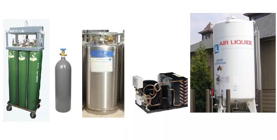
Liquid Nitrogen
Liquid Nitrogen, (L-N2 orLN2) is readily available and widely appreciated for its tremendous cooling capacity. It is available in vacuum insulated somewhat portable tanks (often known as dewars, typically 170 liters) or a large outdoor tank with vacuum jacketed plumbing to the points of use. The use of LN2 allows for easily controlled, nearly unlimited cooling capacity. The downside of LN2 is due to the extreme cold temperatures it is often difficult to handle or lossy due to the heat encroachment from the large differential to ambient temperature. Nevertheless better cost efficiencies can be achieved when you also consider the time saved by the ability to speed up the cooling process. For example in a production environment, waiting for the system to cool down can have a cumulative impact on production capacity. Also note, LN2 in a tank will warm up and vaporize eventually wasting some of the coolants if it is not used within a few weeks. A properly designed distribution system will always have LN2 ready to use.
There are exceptions but generally, distribution systems run around 20 psi. and portable tanks can easily be acquired with pressure ranges 75-120 psi or higher. Higher pressure is recommended when possible due to the shorter latency in waiting for coolant to “cool down the hose” so that liquid is actually coming out the delivery point. Typically a temperature chamber or thermal platform (cold plate AKA hot/cold plates) designed to cool with LN2 will be designed with a coolant orifice of appropriate size to control the flow rate for the specified pressure available. If you need to cool down to very low temperatures or fast, there is little that compares to LN2. Practical systems can often have the capability of cooling down below -150C but in many cases, the ultimate low temperature is limited to -100C because not many other materials are good for those extreme temperatures. Due to the extreme temperature, customers that run systems unattended, cooling with LN2 often specify a redundant safety cooling system shutdown.
Liquid CO2
L-CO2 (Liquid) is often a little cheaper than LN2 but has a more limited lower temperature range of -60C to -65C.
CO2 is available in three basic forms for the lab.
High-pressure Syphon tanks, similar to what you might see in a welding shop. These tanks have a dip tube that takes liquid off the bottom of the tank. The CO2 is stored at room temperature in these high-pressure tanks so the coolant stores indefinitely. This is a good choice if your cooling needs are intermittent or otherwise not extreme. -60C is about the coldest achievable with high pressure CO2
Low-pressure CO2 tanks, similar looking to portable LN2 tanks are pressurized to up to 300 psi and the contents are around -20C in the tank so there are fewer losses than with an LN2 tank which is typical -180C inside.
Distribution systems for supplying CO2 about the facility often distribute the CO2 in gaseous form, condensing, storing, and chilling the coolant at the point of use with a refrigeration compressor. This makes the distribution plumbing system far cheaper than the vacuum jacketed plumbing required for an LN2distribution system
Low-pressure CO2 is more efficient than high pressure CO2.for larger scale regular usage low-pressure CO2 with a satellite distribution system can provide the best cooling economy. There are some trade off’s with each that can be calculated but one other consideration for CO2, especially as delivered from a distribution system is the triple point of this refrigerant. Plumbing systems including inside the thermal test equipment must be designed to not allow the triple point of the coolant to be reached as the coolant in the plumbing can easily turn solid and block up with dry ice. The easiest way to think of this is when the coolant is very cold, never allow the plumbing path to increase in cross-section and subsequently restrict again as this pressure drop can cause the CO2 to turn solid, blocking delivery. This can also happen due to water or other contamination in the system.
Thermoelectric cooling
Thermoelectric cooling products, like many technical products, have experienced minor improvements in reliability cost, and efficiency over the years, however for systems of substantial capacity, they remain more expensive and less efficient than compressor-based systems. The bigger advantages of thermoelectric cooling remain the simplicity of the design and the lacking of the requirement for any pressurized gases oils or refrigerants. Not to dismiss thermoelectric cooling as a viable method for cold testing but the lower heat removal capacity and limited temperature range limits many of their applications. One of the biggest benefits would be most particularly where a cooling module needs to be easily unhooked and hooked up again, the lack pressurized of refrigerant lines, in this case, can be a big benefit. Thermoelectric cooling system temperature ranges are typically from -10C to +70C. Additionally, the fact that it is basically a reversible heat pump can also greatly simplify system designs.
So, to sum it up, if your process can benefit from speed or the capacity is large and LN2 cooling is an option for you, LN2 cooled systems are the best.
If cooling use is only intermittent then often high-pressure CO2 is the best choice.
If the ultimate cold temperatures needed are -55 or above, low-pressure CO2 may be the best choice for its slightly lower cost than LN2 and greater efficiency than high pressure CO2
If LN2 is not readily available for the application or slower transition rates do not impact productivity, refrigeration compressors are often the best choice. For smaller capacity systems, they can often plug directly into normal lab power outlets. Cascade refrigeration systems that are capable of going to temperatures from -40C to -75C are occasionally available for operation on 120v 15 A. power but usually require 230v service or at least a full 20 or 30 A. at 120v. Larger systems with dedicated power of course require more power.
For configurations where the cooling power requirement is fairly small and temperatures will not be required below -10C, thermoelectric systems often provide a favorable solution. This is especially so of the cooling module is expected to be unhooked and rehooked more than one or two times.
Environmental Issues
As we all see increasing concern for the environment, this deserves some comment.
Since the air, we breathe is about 78% Nitrogen, adding or removing Nitrogen from the environment is generally not a problem. However, there really is a limit to the concentration of Nitrogen in breathable air. If the ventilation in the room is limited, Nitrogen can eventually displace the Oxygen required for breathing below 20%. Oxygen concentration below 20% is some cause for concern, below 15% is a good reason to evacuate. If there is ever a question of adequate Oxygen, there are relatively affordable Oxygen monitors that can make an alert if the oxygen in the room is too low.
For CO2, the issue is about the same for Oxygen displacement, there is one small advantage that Carbon Dioxide has a mild scent that can be detected at levels lower than might represent a hazard to humans or other life. The same smell that you might detect from beer or carbonated soda. LN2 on the other hand is odorless.
CO2 has gotten a bad name as a greenhouse gas. There is however not a valid concern about this. Because the CO2 used for cooling has been captured from the atmosphere for this purpose and is simply being returned to where it came from when it is used.
Mechanical refrigeration systems can suffer leaks resulting in the accidental release of greenhouse gasses. Generally, the amount of refrigerant in a small system is not significant in the bigger picture but may represent a long-term concern. The refrigerants used in modern systems pose little or no direct health risk should contact or inhalation occur.
There are no known concerns of environmental hazards with the use of thermoelectric cooling systems.
Call us to talk about your thermal testing requirements.
Liquid CO2 (L-CO2) is a popular refrigerant and is also known as Refrigerant R-744 according to ASHRAE (Formerly the American Society of Heating, Refrigerating and Air Conditioning Engineers). Most of the widely used methods of process cooling involve the vaporization of a liquid to a gas.
Processes like water cooling, air cooling, and thermoelectric cooling would be exceptions, but the cooling process for environmental testing generally involves a phase change, that is the cooling media changes from one state to another, typically from liquid to gas. This phase change process releases what is known as latent heat, the energy that is tied up in the media keeping in the liquid (or solid) phase. This absorption of heat is in addition to the heat that is removed simply by the warmer item warming up the cooler cooling media.
Cryogenic cooling with CO2 utilizes a special case of phase change. Because of its chemical properties, it has no liquid state below 75 psi. It is said to have a triple point instead, where it can simultaneously exist in all three states, liquid, gas, and solid. Most elements or chemical compounds have a triple point at some combination of pressure and temperature ( for example water has a triple point at .088 atmospheres and 0.01 Degrees C.) For CO2 the triple point happens in the range releasing to atmosphere CO2 of normal tank temperatures and pressures. What this means for cooling purposes is that when liquid CO2 is precisely introduced to the system and the pressure is dropped dramatically such as at the nozzle of a spray gun or cooling injector tube on a temperature chamber or thermal platform (cold plate), the liquid quickly turns to dry ice snow, solid-state CO2. As the dry ice warms up, the resulting phase change is the direct change from solid to gas, called sublimation. There is a great release of the latent heat as the CO2sublimates.
Because CO2 readily goes into the solid state for cooling processes, it can sometimes be troublesome if there is some problem that might cause too much coolant to be expanded into a solid at once and cause blockage of the cooling system. It is very important to design CO2 supply and control systems so that the cross-section of the plumbing line never (expands and subsequently) restricts. This will invariably result in dry ice blockage.
Due to the lower costs to capture and compress CO2, it is generally commercially cheaper and for that reason can be a preferable coolant. If your cooling requirements are not as extreme (above -50C), CO2 can be a better choice. A properly designed and maintained system will not suffer blockages due to the sudden solidification of liquid CO2.
High pressure (900 psi) CO2 is generally a little less efficient due to the lower heat of vaporization but it can be a better choice when usage is intermittent as it stores indefinitely at room temperature. Low-pressure CO2(~300 psi) stored in vacuum insulated bottles is often more cost-efficient than LN2. Low-pressure CO2 will store somewhat longer than LN2 because it is stored at about -18C inside the tank as opposed to -190C. By comparison, LN2 can go colder and has greater heat removing capability below -60C, CO2 can be cheaper in larger-scale usage due to its slightly lower volume cost and slightly longer storage times. A couple of further advantages to CO2 cooling is that since it is not nearly as cold upon liquid delivery there, is less loss and consumption delay due to vaporization in the hose. With less vaporization in the hose, delivery time is more predictable upon startup and after longer pauses in usage.
I am sure there are quite a few different answers to that question depending on what you are trying to accomplish.
What is your idea of a high-performance thermal test?
Here is my Top Ten List
Temperature Accuracy: For thermal environmental stimulation or temperature cycling, either from an existing requirement or from developing a deeper understanding of the thermal properties of your system, you need to know that your readings and assumptions are correct to make a meaningful test. Good calibration and multiple sensing points help to better understand what you are working with and the best methods for screening your electronic device under test.
Speed: For good or bad, economics drives things and usually the quicker appropriate testing can be done the better. Increasing throughput is good within the limits that the device can withstand is the goal.
Low Initial and Ongoing Cost: Accurately calculating both initial and ongoing costs can seem foreboding but often can be determined with reasonable accuracy and minimal assumptions. A surprising array of variables are in play however, often some good estimates can be made. Expendable coolant cost and faster test times versus electricity plus the higher maintenance of a refrigeration compressor can be estimated.
Appropriate Automation and Process Verifications as required: A system that automates tests and provides convenient verification by the user, USB removable memory log, or remote communication makes testing more productive.
The Temperature Chamber or Platform is a good fit for the product: Clearly, some products are best tested on a thermal platform (cold plate) and some better in a temperature chamber. The appropriate size of the chamber can increase speed accuracy and otherwise optimize the process. If the product is suitable for testing on a thermal platform, that often will provide the optimal results.
Ease of Use: Portability / Convenience of Operation: In some cases portability, co-location, or benchtop operation of thermal test gear can provide a significant efficiency advantage.
Special Utilities / Services required: Electrical Service, LN2 / Liquid CO2, ventilation: Any special services required are extra costs, some are one-time and some are ongoing that play into the total cost/performance equation.
Lab Space Required: Lab space is a valuable commodity, thermal testing gear that uses less space is better.
Reliability / Support: Clearly nobody wants to sit around with broken equipment when there is testing that needs to be done, reliable and easily serviced equipment is a must.
Safety: I needed 10 items to round out the list so it’s always a good idea to keep safety in mind. With cash being tight, many people choose to modify/repurpose or push older worn-out systems back into service, we can’t ever forget safety so if repurposing always think through and test for safe operation with a few unexpected circumstances before calling it good.
What does high-performance temperature testing mean to you?
I am sure many different things to different people.
In the world of Test and Measurement, there are numerous options for your temperature testing equipment. They can have a significant impact on costs, upfront and ongoing as well as ease and quality of results. For maximum value from your equipment, it is helpful to better understand the methods and choices available to you.
With temperature testing equipment, there is more than one choice for how to accomplish heating and cooling. In most cases, resistance heating is the heating method of choice, thus the primary basis of the decision becomes a discussion of cooling options. For cooling methods, there are several choices and the costs vary dramatically. Finding the best available value for that equipment often depends on determining the specific requirements for your unique application. Here are several factors for your consideration:
When choosing a chamber to meet your needs, good airflow is essential, the air ramp rate of an empty chamber will seem much faster until you put your load inside with a chamber that has low airflow.
As we learn in Physics class, conduction is the most effective process for heat transfer but it is not always possible due to the shape and geometry of the device to test.
In many cases, it comes down to choosing between a chamber or a thermal platform with the shape of the device under test dictating the choice for a chamber. Airstream systems are often a good choice for one at a time component testing but often impractical for production situations where multiple cumbersome systems or queuing of the parts to be tested would be required.
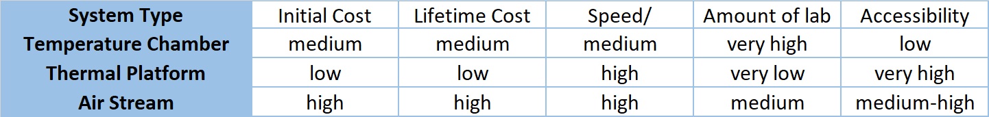
A Summary of the Main Systems Used for Thermal Testing
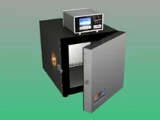
For versatility, standard chambers are very popular and meet the needs of a lot of testing purposes. Often they are more price competitive due to the larger scale market. Again if performance is important pay attention to airflow rates and ramping rates WITH LOAD. Higher performance often means more power, large expensive, noisy compressor systems that require maintenance, or Expendable Cryogenic coolants like L-N2. Chambers provide performance regardless of the shape of the device under test, are typically slower transitioning and settling, and require more lab space.
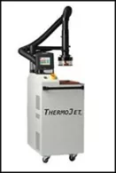
Forced air or airstream systems are very good for spot cooling applications, they are bulkier than thermal platforms but also less sensitive to the shape of the device. They are typically more expensive and require more power and more maintenance. They can provide fast accurate temperature control with better accessibility to the device than chambers.
Platforms control temperature by conductive heat transfer and thus are inherently faster however are restricted to devices that have a flat conductive surface or can be fixtured to work on a platform. They are generally less expensive to buy and operate. Platforms provide fast-cycling time, require little laboratory real estate, and offer very good accessibility to test objects.
The flexibility and ease of use of the temperature controller and the ability to readily produce recorded test records in an automated way is also important consideration for thermal testing value.
As you see, there are several aspects to consider when choosing thermal testing equipment.
If you would like our trained consultants to talk with you and answer any additional questions you may have.
More to follow on methods and value of combined conduction and convection heat transfer.
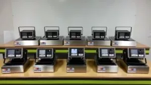
Example of Ten Production Thermal Platform Systems requiring far less lab space and power than other types of thermal test systems.
There are many ways to do thermal testing right, many ways to do thermal testing wrong, and many ways to do a mediocre job with it.
Here are several aspects of thermal testing to consider:
Actually performing a test that is adequate to accomplish the need, requirement, and intent of the testing plan.
The efficiency of time and labor used for the test.
The efficiency of facilities requirements.
Reliability and repeatability of testing.
Heat Transfer by conduction using thermal platforms/hot-cold plates are known to be faster and more efficient but due to complex shapes of many parts not always practical. Heat transfer by convection using temperature chambers that have respectable airflow allows heat to be transferred efficiently to and from irregularly shaped devices. With modern control and monitoring methods, it is now a lot easier to verify that temperatures at specific locations are actually being achieved and held for the specified durations.
The combination of convection and conduction holds several promises of improving the whole thermal testing game. Easily accessible benchtop thermal testing that combines the benefits of convection and conduction allows better performance and accessibility while the unit is under test which is often important for probing or other R & D operations. A small benchtop unit saves time with technicians no longer needing to stop, get up and walk over to a temperature chamber. Smaller batches also mean less waiting in queue for the start of thermal testing. A test stand with a small footprint consumes less precious lab space and uses less power than conventional chambers. Simple L-N2 / L-CO2 cooled systems are quite fast, economical, have very low maintenance requirements.
Modern controllers are easily automated with Ethernet, GPIB, FTP, email, logging, web server, network printing and texting capability will keep test operators informed of testing status and expedite accurate reporting of test results.
TotalTemp Technologies offers advanced thermal testing systems, off the shelf and custom engineered systems. Call today to talk with experienced representatives that help plan the best solution for your testing requirements.
Replacing programmable instruments, keeping software compatibility in an automated test
When an instrument eventually goes obsolete or for any other reason a new instrument is put in place of one that is already a part of an automated test system, some programming work will follow to make the transition complete. Even if the instruments are supposed to be software compatible, there are often minor details to tend. The good news is that it is usually not that difficult or involved. Of course, exceptions can be noted but usually, it is not as big of a project as some anticipate.
We have had programmable test equipment with us now for well over fifty years and a lot has been written about making instruments easier to program. Indeed great progress has been made and hopefully, at some point in the future, and inclusive common language such as SCPI (Standard Commands for Programmable Instruments) for all test gear could be fully in place, functional, and accepted by all manufacturers. This type of command structure may be more deterministic with some instruments than others, however at this point in time it seems to remain a fact that different programmable instruments evolved over different courses of development, in particular, temperature chambers, so I believe there will ultimately remain a few little details one should be prepared to attend to whenever swapping these instruments.
The following is an example of the methodology used to transition from communicating a Sigma temperature controller to Tidal Engineering’s Synergy line of temperature controllers used by TotalTemp Technologies. Outlined are the comparisons of the two different command strings and expected responses.
Without getting into software specifics such as conditional code and so on – This is how we make it work without a lot of difficulties. (App note produced by Tidal Engineering (www.tidaleng.com)
Thermal Testing with Conduction? – Double Check your true area of Contact!
To achieve the benefits of thermal testing with conduction, thermal platforms also known as Hot/Cold Plates are used to force devices to specific temperatures. While Thermal Platforms may not work for every application, where they do, they offer a distinct advantage in speed, accessibility, efficiency, and production throughput. Items with irregular surfaces or even vials or beakers can often be fixtured to work well on a platform and allow for much better cost efficiency than found with temperature chambers.
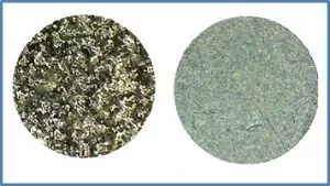
For heat transfer reasons, the best physical configuration for the Device Under Test (DUT) is one with a flat thermally conductive surface and low profile. Think something shaped like a book. However, the term “flat” can be critical when it comes to proper, efficient thermal conduction testing. Typically, the surface of most thermal platforms is Blanchard or disc ground to within 0.005”. Likewise, the bottom surface of the DUT must be very flat too for good heat transfer.
If the bottom of the DUT had just the slightest bow to it, even only a few thousandths of an inch, sometimes no appropriate amount of pressure can accomplish full surface to surface contact. The bottom of the DUT could easily be missing a large area of contact, occasionally a surprising amount of the surface is not in contact at all. You can often get a good visualization of the surface flatness by placing a flat straightedge against the bottom of your device. Additionally, microscopic surface variations are very important. The following, on the left, is a microscopic picture (200x) of an aluminum surface that would look perfectly flat to the casual viewer. You can see a very small percentage of the surface would actually be available for contact. On the left, a Blanchard ground surface maintains much better overall flatness at the microscopic level.
Anodized Wrote aluminum on Left, Cast Blanchard Ground plate on Right
Losing a large percentage of contact between the DUT and platform surface can be hugely wasteful of resources and you may not be performing the test you think. it can definitely affect production throughput as consideration for improving thermal performance. Let’s talk about some ways to resolve and/or improve this issue:
Thermal Grease – The heat transfer can be improved by applying thermal grease between the surfaces. Especially when the surfaces cannot be made as flat as desired. Much has been written, some of it contradictory within the realm of high-performance CPUs regarding the best thermal grease. If you can achieve flat surfaces little or no grease will be required.
A few things to remember about thermal grease:
Grease never conducts as well as metal but is always better than air.
Usually, less is better.
Grease is messy and often not reusable.
There are a lot of different greases, for practical purposes, standard white silicone grease such as Wakefield 120 works about as well as any.
If you can’t keep the grease clean, start over. LIGHT circular sanding with scotchbrite (the abrasive on kitchen sponges) or similar will smooth and clean the surface best. Wipe with denatured alcohol if necessary to make sure surfaces are clean and particle-free.
Your results may vary depending on the application.
It is important to have flatness so good that you cannot detect any gaps between surfaces. This becomes more challenging as surfaces become larger. When you are unable to improve the flatness of your DUT, or force good surface to surface contact with adequate pressure, then using thermal grease to fill the voids can be very helpful. That is all thermal grease is really good for, replacing the insulating factor of air, with something that is somewhat less insulating and more conductive. Thermal pads are an alternative to grease, they transfer heat less effectively but are easier to use and less messy than grease.
Fastening Down the DUT – You have the option of ordering custom hole patterns in the plate surface to match your DUT screw-down pattern. Even the size of the hole and thread count can be called out to meet your specific application. This is a very common and probably the best way to secure the DUT to the plate. It is best to order the hole pattern at the same time as the platform so they are machined into the plate surface prior to anodizing, and assembly. In some cases, these holes can be drilled after purchase, but definitely consult the plate manufacturer first, to ensure you have adequate clearance. Drilling too deep into a heater or cooling channel can be an expensive mistake.
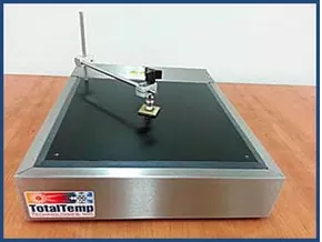
Clamping the DUT down to the Plate Surface – This can be a fairly efficient way to improve DUT to plate surface contact. In some cases depending on the size of the DUT, several clamps can be used. Typically, the clamps are attached to the plate surface with a threaded post. If your manufacturer does not provide threaded holes in the plate surface as a standard feature, you will likely want to specify that option when purchasing.
Clamp Set on a Thermal Platform. Threaded mounting holes come as a standard feature.
Lastly, some users rely on the weight of the DUT itself to provide adequate contact. Some will add weights to the DUT, care must be taken so that the added mass does not cause damage or add more of a thermally conductive load to the test. Adding weights would be the least desirable method for attempting good DUT to plate surface contact.
When looking to purchase new, it is highly advisable that you speak to the Sales Engineer about the methods and options available from them for securing the DUT to their thermal platform.