Engineering teams invest considerable time and resources developing their devices under test, yet many still risk losing these valuable units because they operate without a proper fail-safe system in place. When a thermal runaway event occurs, the consequences can be severe, ranging from major monetary losses to unscheduled delays and even jeopardizing the success of a critical program. TotalTemp’s fail-safe architecture eliminates this failure mode by removing power during abnormal thermal conditions,
protecting both the test system and the high-value test article.
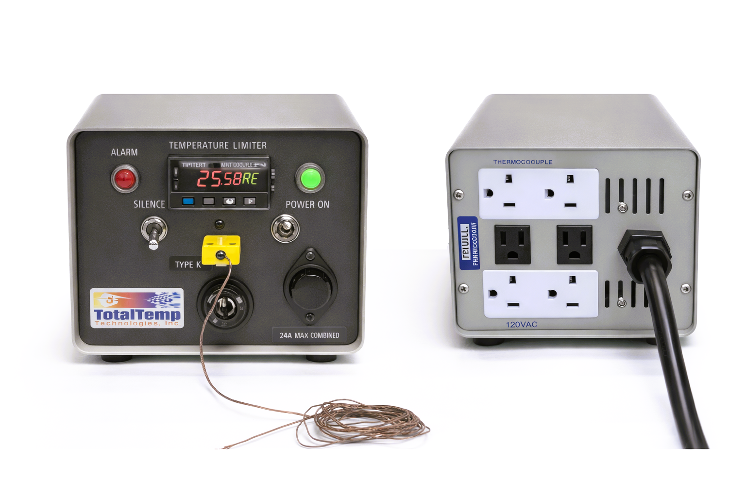
TotalTemp’s Independent Thermal Fail-Safe Systems provide a truly independent layer of protection for any thermal test environment. Operating outside the primary temperature controller, the IFS is designed to shut down heating, cooling, or DUT (Device Under Test) power when preset temperature limits are exceeded.
This creates a reliable, redundant safeguard against thermal runaway, unintended cooling, loss of cooling capacity, or DUT active-load overheating. IFS units can be retrofitted to most Thermal Platforms, Temperature Chambers, Hybrid Chambers, or custom thermal
systems. Each system is configurable for high-limit or low-limit protection and supports thermocouple or RTD sensing. Audible alarms, visual indicators, and optional digital notifications (via Synergy Nano) provide clear
operator awareness during both attended and unattended testing.
Rackmount and benchtop configurations are available, covering temperature ranges from –200 °C to +1260 °C suitable for ESS, space simulation, cryogenic testing, and high-temperature materials evaluation.
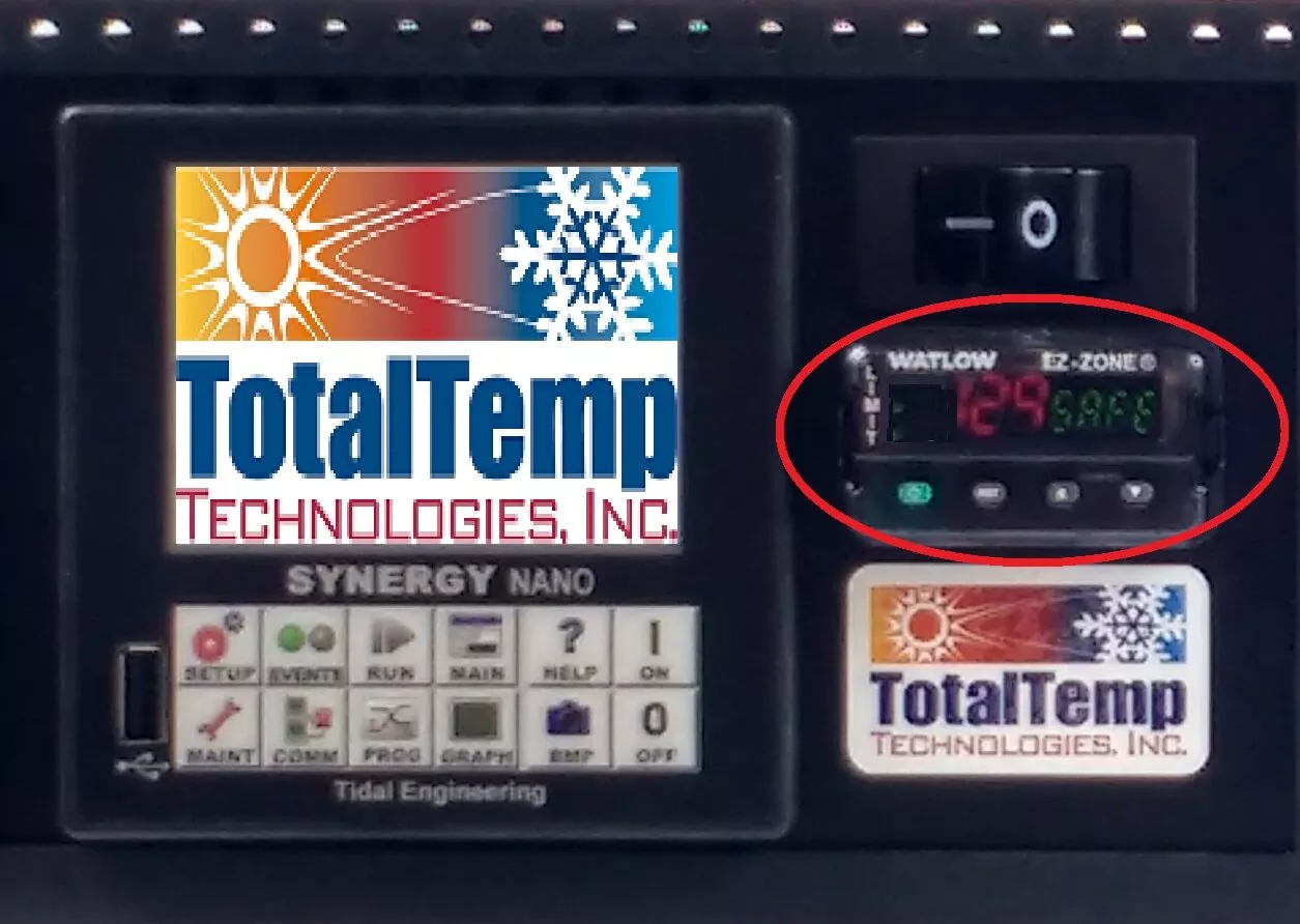
The red circle in Figure 2 indicates the redundant high/low-limit temperature controller. A redundant fail-safe with a limit controller works differently than the IFS. It uses an independent RTD sensor to monitor temperature and actuates a redundant cryogenic cutoff valve to physically stop LN₂ flow during cold-runaway scenarios caused by primary valve failure.
In addition to closing the valve, the redundant controller also cuts power to the main relay, removing power from heaters and blowers while keeping the controller energized. Together, the valve and relay shutdown ensure the
chamber or platform cannot continue cooling or heating during an equipment failure, protecting the device under test.
Summary:
IFS = external, controller-independent electrical shutdown
Redundant Fail-Safe = internal, cryogenic-specific mechanical + electrical shutdown. Using both creates a layered, highly robust safety architecture.
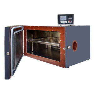
Figure 3: Temperature Chamber example, Model C460-N

Figure 4: TotalTemp Dual Thermal Platform, Model SD49/98
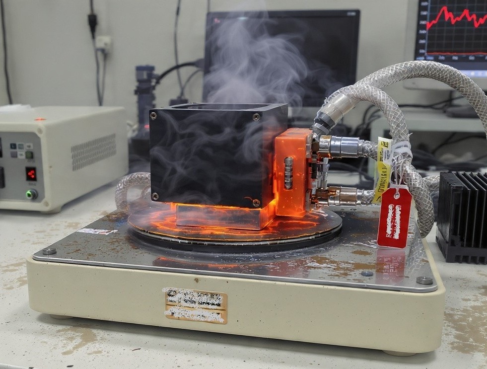
Scenario: An ESS thermal platform is ramping quickly when a heater relay sticks (SSR TRIAC latches closed).
Fail-Safe Response:
Benefit: Prevents overheating damage, ignition events, or destruction of expensive flight or mission-critical electronics.
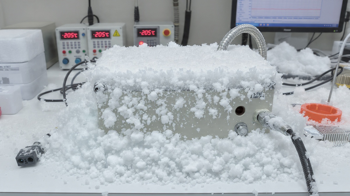
Scenario: A cryogenic cooling valve sticks open or the primary controller fails low, driving the system far below the intended setpoint.
Fail-Safe Response:
Benefit: Protects optics, composites, adhesives, and aerospace hardware from cracking or embrittlement due to unintended deep-cold excursions.
Scenario: A DUT generates significant internal heat. If the cooling subsystem fails — blocked coolant flow, compressor fault, pump failure, or depleted LN₂/CO₂ supply — the platform can no longer remove heat. Even with heaters off, the DUT temperature rises due to its own internal power dissipation.
Independent Fail-Safe Response:
Benefit: Prevents DUT burnout, battery thermal events, or runaway heating in RF, laser, or avionics modules — including during long or unattended tests.
Temperature chambers and thermal platforms inherently carry risks when operating at extreme temperatures.
Protecting both the test article and the equipment requires multiple layers of safety:
TotalTemp’s Independent Thermal Fail-Safe Systems provide a fully independent layer of protection for thermal test
environments and ESS applications. Operating separately from the primary temperature controller, they automatically shut down heating, cooling, or DUT power when preset temperature thresholds are exceeded.
This architecture delivers a redundant safeguard against thermal runaway, unintended cooling, loss of cooling capacity, and active-load overheating. Each unit supports high- or low-limit protection using thermocouple or RTD
inputs. Audible alarms, visual indicators, and optional digital notifications via the Advanced Synergy Nano controller ensure clear operator awareness during both attended and unattended testing.
In our next blog, we will cover essential maintenance and monitoring practices to ensure smooth, trouble-free, and time-efficient thermal testing. For more information about our Independent Fail-Safe and Redundant Fail-Safe
systems, please contact us — we are always happy to support.
© 2023 TotalTemp Technologies | All Rights Reserved |