What is High Performance Thermal Testing?

What is High Performance Thermal Testing?

I am sure there are quite a few different answers to that question depending on what you are trying to accomplish.

What is your idea of a high-performance thermal test?

Here is my Top Ten List

Temperature Accuracy: For thermal environmental stimulation or temperature cycling, either from an existing requirement or from developing a deeper understanding of the thermal properties of your system, you need to know that your readings and assumptions are correct to make a meaningful test. Good calibration and multiple sensing points help to better understand what you are working with and the best methods for screening your electronic device under test.

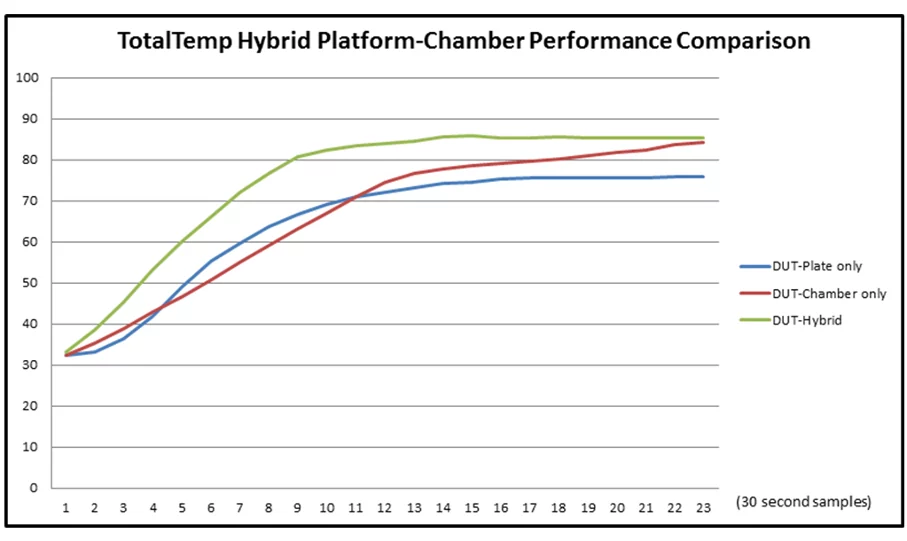
Speed: For good or bad, economics drives things and usually the quicker appropriate testing can be done the better.  Increasing throughput is good within the limits that the device can withstand is the goal.

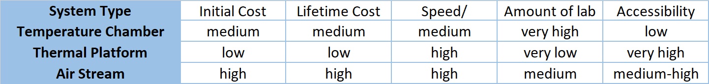
Low Initial and Ongoing Cost: Accurately calculating both initial and ongoing costs can seem foreboding but often can be determined with reasonable accuracy and minimal assumptions. A surprising array of variables are in play however, often some good estimates can be made. Expendable coolant cost and faster test times versus electricity plus the higher maintenance of a refrigeration compressor can be estimated.

Appropriate Automation and Process Verifications as required: A system that automates tests and provides convenient verification by the user, USB removable memory log, or remote communication makes testing more productive.

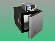
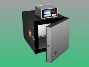
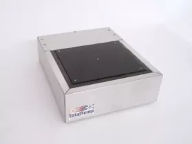
The Temperature Chamber or Platform is a good fit for the product: Clearly, some products are best tested on a thermal platform (cold plate) and some better in a temperature chamber.  The appropriate size of the chamber can increase speed accuracy and otherwise optimize the process. If the product is suitable for testing on a thermal platform, that often will provide the optimal results.

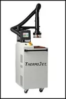
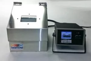
Ease of Use: Portability / Convenience of Operation: In some cases portability, co-location, or benchtop operation of thermal test gear can provide a significant efficiency advantage.

Special Utilities / Services required: Electrical Service, LN2 / Liquid CO2, ventilation: Any special services required are extra costs, some are one-time and some are ongoing that play into the total cost/performance equation.

Lab Space Required: Lab space is a valuable commodity, thermal testing gear that uses less space is better.

Reliability / Support: Clearly nobody wants to sit around with broken equipment when there is testing that needs to be done, reliable and easily serviced equipment is a must.

Safety: I needed 10 items to round out the list so it’s always a good idea to keep safety in mind.  With cash being tight, many people choose to modify/repurpose or push older worn-out systems back into service, we can’t ever forget safety so if repurposing always think through and test for safe operation with a few unexpected circumstances before calling it good.

What does high-performance temperature testing mean to you?

I am sure many different things to different people.

Let me know what it means to you.

Thermal Testing Equipment: Maximizing Value

Thermal Testing Equipment: Maximizing Value


In the world of Test and Measurement, there are numerous options for your temperature testing equipment. They can have a significant impact on costs, upfront and ongoing as well as ease and quality of results. For maximum value from your equipment, it is helpful to better understand the methods and choices available to you.

With temperature testing equipment, there is more than one choice for how to accomplish heating and cooling. In most cases, resistance heating is the heating method of choice, thus the primary basis of the decision becomes a discussion of cooling options. For cooling methods, there are several choices and the costs vary dramatically. Finding the best available value for that equipment often depends on determining the specific requirements for your unique application. Here are several factors for your consideration:

Methods of Cooling 

Mechanical Refrigeration, – Closed-loop compressor-based systems.

Expendable Coolants – Cryogenics i.e. Liquid Nitrogen (L-N2) or Liquid Carbon Dioxide (L-CO2).

Thermoelectric Cooling – Peltier Chiller Systems.

Recirculating Fluid Chiller Systems and Liquid Baths.

For more details on the cooling method trade-offs visit our  blog post:

Methods of Heat Transfer 

Convection –

Temperature Chambers/recirculating air or Forced.

Air Systems, non-recirculating air such as a thermal airstream system.

Conduction –  Thermal Platforms.

See our whitepaper on Conduction v. Convection for Thermal testing.

When choosing a chamber to meet your needs, good airflow is essential, the air ramp rate of an empty chamber will seem much faster until you put your load inside with a chamber that has low airflow.

As we learn in Physics class, conduction is the most effective process for heat transfer but it is not always possible due to the shape and geometry of the device to test.

In many cases, it comes down to choosing between a chamber or a thermal platform with the shape of the device under test dictating the choice for a chamber. Airstream systems are often a good choice for one at a time component testing but often impractical for production situations where multiple cumbersome systems or queuing of the parts to be tested would be required.

A Summary of the Main Systems Used for Thermal Testing


For versatility, standard chambers are very popular and meet the needs of a lot of testing purposes.  Often they are more price competitive due to the larger scale market. Again if performance is important pay attention to airflow rates and ramping rates WITH LOAD.  Higher performance often means more power, large expensive, noisy compressor systems that require maintenance, or Expendable Cryogenic coolants like L-N2. Chambers provide performance regardless of the shape of the device under test, are typically slower transitioning and settling, and require more lab space.

Forced air or airstream systems are very good for spot cooling applications, they are bulkier than thermal platforms but also less sensitive to the shape of the device.  They are typically more expensive and require more power and more maintenance.  They can provide fast accurate temperature control with better accessibility to the device than chambers.

Platforms control temperature by conductive heat transfer and thus are inherently faster however are restricted to devices that have a flat conductive surface or can be fixtured to work on a platform.  They are generally less expensive to buy and operate.  Platforms provide fast-cycling time,  require little laboratory real estate, and offer very good accessibility to test objects.

The flexibility and ease of use of the temperature controller and the ability to readily produce recorded test records in an automated way is also important consideration for thermal testing value.

As you see, there are several aspects to consider when choosing thermal testing equipment.

If you would like our trained consultants to talk with you and answer any additional questions you may have.

More to follow on methods and value of combined conduction and convection heat transfer.

Example of Ten Production Thermal Platform Systems requiring far less lab space and power than other types of thermal test systems.

Expeditious Thermal Testing Visited Anew

Expeditious Thermal Testing Visited Anew


There are many ways to do thermal testing right, many ways to do thermal testing wrong, and many ways to do a mediocre job with it.

Here are several aspects of thermal testing to consider:

  1. Actually performing a test that is adequate to accomplish the need, requirement, and intent of the testing plan.
  2. The efficiency of time and labor used for the test.
  3. The efficiency of facilities requirements.
  4. Reliability and repeatability of testing.

Heat Transfer by conduction using thermal platforms/hot-cold plates are known to be faster and more efficient but due to complex shapes of many parts not always practical.  Heat transfer by convection using temperature chambers that have respectable airflow allows heat to be transferred efficiently to and from irregularly shaped devices. With modern control and monitoring methods, it is now a lot easier to verify that temperatures at specific locations are actually being achieved and held for the specified durations.

The combination of convection and conduction holds several promises of improving the whole thermal testing game.  Easily accessible benchtop thermal testing that combines the benefits of convection and conduction allows better performance and accessibility while the unit is under test which is often important for probing or other R & D operations. A small benchtop unit saves time with technicians no longer needing to stop, get up and walk over to a temperature chamber. Smaller batches also mean less waiting in queue for the start of thermal testing. A test stand with a small footprint consumes less precious lab space and uses less power than conventional chambers. Simple L-N2 / L-CO2 cooled systems are quite fast, economical, have very low maintenance requirements.

Modern controllers are easily automated with Ethernet, GPIB, FTP, email, logging, web server, network printing and texting capability will keep test operators informed of testing status and expedite accurate reporting of test results.

TotalTemp Technologies offers advanced thermal testing systems, off the shelf and custom engineered systems. Call today to talk with experienced representatives that help plan the best solution for your testing requirements.

Check out our new product combining the advantages of thermal testing with both convection and conduction: https://www.totaltemptech.com/totaltemp-hybrid-benchtop-chamber/

Replacing programmable instruments, keeping software compatibility in an automated test

Replacing programmable instruments, keeping software compatibility in an automated test

When an instrument eventually goes obsolete or for any other reason a new instrument is put in place of one that is already a part of an automated test system, some programming work will follow to make the transition complete.  Even if the instruments are supposed to be software compatible, there are often minor details to tend.  The good news is that it is usually not that difficult or involved. Of course, exceptions can be noted but usually, it is not as big of a project as some anticipate.

We have had programmable test equipment with us now for well over fifty years and a lot has been written about making instruments easier to program. Indeed great progress has been made and hopefully, at some point in the future, and inclusive common language such as SCPI (Standard Commands for Programmable Instruments) for all test gear could be fully in place, functional, and accepted by all manufacturers.  This type of command structure may be more deterministic with some instruments than others, however at this point in time it seems to remain a fact that different programmable instruments evolved over different courses of development, in particular, temperature chambers, so I believe there will ultimately remain a few little details one should be prepared to attend to whenever swapping these instruments.

The following is an example of the methodology used to transition from communicating a Sigma temperature controller to Tidal Engineering’s Synergy line of temperature controllers used by TotalTemp Technologies. Outlined are the comparisons of the two different command strings and expected responses.

Without getting into software specifics such as conditional code and so on – This is how we make it work without a lot of difficulties.  (App note produced by Tidal Engineering (www.tidaleng.com)

Synergy Controller Application note 111

Please share your experiences with swapping instruments and compatibility between programmable instruments that perform the same function.

Spot Cooling with Vortex Tubes – a Viable Option

Spot Cooling with Vortex Tubes – a Viable Option

When using temperature chambers or thermal platforms to do thermal testing, the heating of devices tends to be more or less straightforward. Generally, electrical resistance heating, be it conductive or convection (or even radiant) is the best, cheapest, and most easily controllable method.

However when it comes to cooling, there are a few more options, the primary ones being mechanical refrigeration, expendable cryogenic gas such as L-CO2 or L-N2,  Peltier (thermoelectric), or – for some, generally smaller applications, vortex tubes are also an option.

Not to be confused with ordinary Venturi tubes, the official name of the device is the Ranque-Hilsch vortex tube.  These clever devices are able to provide a surprising amount of refrigeration capacity from compressed air alone.  They are best for small lower-cost spot cooling applications since they are a lot simpler and easier to maintain than refrigeration systems. They are somewhat less efficient at cooling than a typical refrigeration system.  Efficiency is comparable to Peltier cooling.

The summary description of the operation from Wikipedia:  Pressurized gas is injected tangentially into a swirl chamber and accelerated to a high rate of rotation.  Due to the conical nozzle at the end of the tube, only the outer shell of the compressed gas is allowed to escape at that end.  The remainder of the gas is forced to return in an inner vortex of reduced diameter within the outer vortex…

The main physical phenomenon of the vortex tube is the temperature separation between the cold vortex core and the warm vortex periphery.  The vortex tube is essentially a rotors turboexpander.   It consists of a rotor’s radial inflow turbine (cold end, in the center) and a rotors centrifugal compressor (hot end on the periphery).  The work output of the turbine is converted into heat by the compressor at the hot end.  This explanation of the heating/chilling effect stems from the law of energy conservation.

For the practical application, a small vortex tube with 100 psi room temperature air and an available flow rate of 5-10 SCFM can produce a temperature drop of 50 degrees C and removal of 2800 BTU/Hr., or around 800 Watts.

A couple of realistic concepts and limitations to using vortex tubes:

1.  Air source must be clean and of good capacity per above, this will enable long life with little or no maintenance

2.  Use of proper muffler is suggested to minimize exhaust noise

3.  Small active loads on cold plates or chambers will work well with vortex tubes

4.  Systems can be optimized for more capacity or more temperature differential.

5.  Properly integrated into a hot-cold plate or small chamber, a vortex tube chiller may be the best choice for small low capacity cooling needs.

TotalTemp Technology is happy to talk with you about your thermal testing requirements.

Feel Free to reach out with your questions.

RTD’s v. Thermocouples, which is best?

RTD’s v. Thermocouples, which is best?

RTDs v. Thermocouples

The question is often asked, “what is the best temperature sensor for my temperature testing or environmental testing application?”

The answers can vary a lot but the two main leaders of the pack are RTDs (Resistance Temperature Detector) followed by Thermocouples.

If you are looking for the short answer of which is best, it is RTD’s but here is a little more to the story

The primary reasons RTD are best:

Better long-term stability, more linear response, More gain- that is more signal change for a given temperature change, also they have easier to manage lead wire connections.

So why would someone choose a Thermocouple over an RTD?

Arguments in favor of Thermocouples:

The number one reason – Thermocouples are cheaper.  Market demands often dictate cheaper.

Thermocouples generally hold up better in environments of severe vibration or thermal shock.

They typically are better for point sensing instead of sensing a larger area or air temperature.

Stepping back a little: There are more tradeoffs, but those are the main considerations. To be fair, there are other viable temperature sensors for many applications but just a short history lesson first. German Physicist Thomas Johann Seebeck first discovered in 1821 that any junction of dissimilar metals will produce an electric potential related to temperature.  Thus the name for a device that senses temperature by the coupling of two metals.  The result was the first electronic temperature sensing device and it could be designed to work without any external power source. A couple of issues about how this sensor works are: 1) The carefully controlled types of metals in the sensor used have to be continued all the way to the instrument that is measuring the temperature. 2) The instrument itself requires an additional thermocouple to be used as a fixed reference.  Since the temperature of the fixed reference usually changes, often an additional RTD or bandgap sensor is used to compensate for the thermocouple calibration.

In 1871 Sir William Siemens discovered the Resistance Temperature Detector or RTD.  He found that Platinum wire and other materials have a well-defined relationship between temperature and the electrical resistance of the material.  The relationship between temperature and ohms is much more linear and easier to work with than the relationship between volts and temperature with thermocouples.

Thermistors are simply a specific type of RTD, often made with a polymer or cheaper materials than Platinum.  They typically have a narrower temperature range and have less long-term accuracy. Also as a side note, Thermistors most often but not always have a Negative Temperature Coefficient (NTC), meaning that they have less resistance as temperatures get higher.  This feature makes them handy for several special compensation applications, for example canceling out other factors that increase with temperature.

The Bandgap (transistor) Temperature Sensor is one other significant, modern temperature sensor.  This device makes use of the known effect that the forward Base to Emitter voltage of any transistor is directly and predictably affected by temperature.  These devices although rarely used in applications such as temperature chambers are popular because they are inexpensive and can be easily integrated into other silicon circuits making internal component temperature sensing very simple and affordable.  Their usability is primarily limited to the range of -40C to +200C.

RTDs are widely accepted as the preferred temperature sensor for long-term repeatability.  It is my position that they will continue to prevail as “the best quality sensor” however I do hear some interesting reports that there have been recent improvements to the technology of making and reading thermocouples.  I think the jury is still out but I would be interested to hear what experiences others have had with a so-called new generation of thermocouples and available accompanying 24-bit A/D sensing circuits.

As a final note, there are several distinctions between types of thermocouples and likewise different types of RTDs.  The thermocouple type must match the type the instrument is configured to read.  In the same manner, the RTD must match the curve (Typically DIN curve) the controller is configured for.  Additionally, the RTD has a base resistance value that must match controller configuration (typically 100 ohms at 0C)

If you want to know more, just ask.

TotalTemp Technologies offers a selection of 100 and 500 ohm RTDs and thermocouples for thermal platforms and other applications.

Our experienced team can provide assistance with your temperature sensing, hot/cold plate controlling, and thermal testing needs.

Thermal Testing with Convection and Conduction… together at last!

Thermal Testing with Convection and Conduction… together at last!

A Marriage Made in Heaven?
[Who could know, but now we do]

The Hybrid Benchtop Chamber – True Thermal Testing Bliss

Combines Thermal Conduction and Convection
in one incredibly fast and efficient design

A heartfelt Congratulation is in order for the happy and successful union of two distinct thermal testing methods that are finally sharing the same dance floor together – as the first true Hybrid.  To better understand the specific benefits from both sides of this collaboration of two testing methods, please review the following white paper:

Conduction vs. Convection for Thermal Testing

Typical Environmental Test Equipment used for Thermal Convection and Thermal Conduction

Thermal testing by convection is usually achieved with the use of a Temperature Chamber.  For versatility, standard chambers are very popular and meet the needs of a lot of testing purposes.  Chambers provide performance regardless of the shape of the device under test, are typically slower transitioning and settling, and require more lab space.

Temperature Chamber

Thermal testing by conduction is most commonly done on a Thermal Platform.  Platforms control temperature by conductive heat transfer and thus are inherently faster however are restricted to devices that have a flat conductive surface or can be fixtured to work on a platform.  Platforms provide fast-cycling time, require little laboratory real estate, and offer very good accessibility to test objects.

Thermal Platform (Coldplate)

Hybrid Benchtop Test Equipment Solves Many Problems

* Improves thermal uniformity gradients

* Increases throughput with faster cycle times

* Small footprint with easy access benchtop operation

* The fully-featured Synergy Nano Temperature Controller is capable of controlling platform temperature and air temperature independently or together

* Controller offers DUT and other data logging, remote access, cloud capability, and many networking functions

Click here: Hybrid Benchtop Chamber Flyer Datasheet

Hybrid Benchtop Chamber Test Equipment

Shown with Lid up revealing the Thermal Platform floor of the Chamber

Thermal testing is an important part of electronic manufacturing for reliability and design verification.

There are a variety of products for thermal testing and now TotalTemp is presenting a completely new and unique contender.

Temperature chambers, thermal platforms, air forcing units, and liquid baths have been around for a while and work well with many types of testing requirements.   But the Hybrid Benchtop Chamber Test Equipment provides many of the best features of Temperature Chambers and Thermal Platforms together to maximize performance and control and shows new promise of filling the need for faster, superior thermal testing.

Hybrid Benchtop Chamber Has Performance Results

As shown in the data chart above, in the basic operation mode, The Hybrid Benchtop Chamber demonstrates a significant improvement in thermal test performance.  The floor of the chamber is a completely functioning Hot/Cold Plate and operates independently or in conjunction with the chamber.

Because the controller is capable of advanced temperature control algorithms, it can allow even better performance by monitoring DUT temperature and allowing air and platform temperatures to be carefully controlled while verifying that required DUT temperatures are achieved.

The standard model currently available is called the HBC49-N with a thermal platform size of 6.5” D x 7.5” W, the chamber interior dimensions are  8.5” W x 7.5” D, Height is 4.5” to 6.5” at the rear.  The system can be cooled with liquid nitrogen (L-N2) or liquid carbon dioxide (L-CO2) and is rated for a temperature range of -100°C to +150°C.

TotalTemp Technologies is the manufacturer of the Hybrid Benchtop Chamber.  TotalTemp is a manufacturer of temperature cycling and conditioning equipment.  They are located in San Diego, CA.

Cost effective wide range thermal testing

Cost effective wide range thermal testing

Testing at extreme temperatures requires considering several options. Testing at hot temperatures has its issues, however, testing at ultracold temperatures – below -40 C in most cases requires the use of expensive and sometimes failure-prone cascade refrigeration systems or alternately applying expendable cryogenic fluids such as liquid nitrogen or liquid CO2.

High-performance cooling is often more of a challenge than heating and also tends to be the least understood process.  The high initial cost is a well-known roadblock to acquiring the best equipment to do the job. Often the unknown or under-reported cost of running a refrigeration system, electricity, maintenance plus possible downtime also require consideration. When thinking of expendable coolant solutions, facilities managers often have some pushback to pressurized liquid Nitrogen or other cryogenic fluids.  Cryogenic fluid distribution systems can be another convenient and safer alternative to large tanks. Unless there are consistent and large-scale uses they are often not warranted due to the extreme installation costs.


10-liter tank on a lightweight portable cart

These safe and effective portable systems solve many Cryogenic Temperature testing requirements.

Moving Forward

Another often overlooked option for testing at extremely cold temperatures is a low-pressure Liquid Nitrogen system. I am referring to is a small portable low-pressure LN2 tank. For example, if you have a 20-liter portable tank you can carry the tank easily by yourself or transport it on a light-duty cart. It will store (with some loss) for well over a month, and best of all you can hold a thermal platform at any other similarly efficient (if it is such) thermal testing system at -50C for hours or ramp to -50C several times without refilling or swapping tanks.   Doctor’s offices often use small portable LN2 tanks with just enough pressure to make the Nitrogen come out of a nozzle.  Similar systems can be used to provide cryogenic cooling to small chambers or thermal platforms.  Sometimes these systems can safely have their pressures boosted by a small amount to achieve really good performance.

New technologies are helping Liquid Nitrogen generating systems be more widely available. Systems such as Elan2 products make homemade LN2 a cost-effective, efficient cryogenic cooling strategy.

Contact us if we can help with any concerns you may have about cryogenic cooling for environmental testing.

Evaluating Thermal Imaging for Temperature Test

Evaluating Thermal Imaging for Temperature Test

Initial FIndings

We acquired a FLIR ONE for Android from sources online, they are about $250 in most places. So the question is Toy or valuable tool. My opinion is Both! Not to deny the fun factor, (it is important to enjoy your job, right?) I say very much more on the useful tool side.  In the 90’s we paid more than that just to bring our products to a facility that allowed us to do some brief tests with less conclusive results. Laboratory grade thermal imagers still have a comma in the price tag and go upward from there.  This unit is primarily marketed as an uncalibrated tool but I found that the Flir One gives some very useful relative readings for testing and evaluating purposes.  As for absolute temperature readings, there is still a little something to be desired. The unit’s instructions are a little vague regarding measurement accuracies but the on-screen spot reading is quite useful.  The FLIR One unit offers better image quality and measures tenths where other units such as the Seek Compact thermal imager show readings with less precision.

Emissivity is an important factor in thermal imaging. Per the Wikipedia link here, emissivity is the effectiveness of a surface in transmitting energy as thermal radiation.  A cat would have very low emissivity whereas a black anodized aluminum surface would have nearly 1.0 emissivity. Professional grade and Non-imaging handheld thermometers all struggle some with emissivity. This unit has four different emissivity settings.

Useful Findings

For our Thermal Platform Business as you might expect it is useful in demonstrating the advantages of the thermal platforms and our Hybrid Benchtop Chamber over other environmental test equipment or thermal testing gear.

Examples here show a Thermal Platform heating up with locations of heaters evident and then a few seconds later stabilized at a hot temperature.

Thermal Platform heating to the temperature

In this case, further adjustment of the camera’s emissivity settings allowed more accurate absolute readings.

The thermal imager is also very useful in finding gradients during thermal tests and hot spots due to internal device heating or “convection shadows” which frequently happen with standard temperature test chambers.

Sensitive Relative Readings

Here is a surprising little demonstration.  Having a foot on the carpet for just 20 seconds, the heat transmitted through a thick boot sole and sock shows up as 2-3 tenths of a degree temperature gradients several seconds after the foot was moved.  More specific thermal test examples to follow but you can see how this tool would be useful to evaluate thermal stresses in electronic and power control systems.

Here are what I feel to be the takeaway points:

  • Quick easy and low-cost demonstration of temperatures differentials.
  • Accurate absolute temperature readings are more challenging.
  • Paying attention to the unit under test emissivity helps achieve more accurate results.

Is Thermal Testing a Necessary Evil? – Made Better Here

Is Thermal Testing a Necessary Evil? – Made Better Here

Automation makes it easier

I am thinking a certain number of test engineers feel that thermal testing is more of a necessary evil than a joyful endeavor. Well, we are here to make things fall as much as possible onto the side of the joyful endeavor.

How does that play out in the real world? My thoughts include several aspects of thermal testing that can make it feel more like a joyful endeavor.

1) Knowing that you are working toward a goal of making tested, and reliable hardware can make it feel like valued work.  People don’t enjoy making junk.

2) Not following an arbitrary script but doing real verification, tracking results with the ability to easily analyze and not a lot of manual parsing of data also makes it more enjoyable and improve quality.

3) When done correctly automating a process will produce easier, more consistent good results.

4) Traceability – Providing a detailed written report without spending hours toiling over numbers easily proves that the job was done correctly.  Thermal testing is all about verification, Right?

5) Saving money is generally a good thing, hopefully, more profits, eventually more for the people who do the work too.

The Synergy Nano temperature controller helps to achieve the above goals with automation plus precise temperature control. Just one instrument is required to produce printed results whereas in many cases these results might require several expensive pieces of equipment and hands-on data manipulation.  The Synergy Nano has easy-to-use interfaces that can provide communication over Ethernet, serial, GPIB front panel, and other means. Logging several DUT temperature points is easy. Ramp and dwell profiles can be loaded by a user or by computer then stored/transferred as needed. Remote monitoring in real-time via a web server is easy as well. FTP data transfer or front panel graphing and thumb drive capture add flexibility. Logging of setpoints, numerous data options, even PID information or system, and DUT temperatures complete the picture.

A real big-time saver and the main point of this conversation is quickly producing documented results. Synergy Nano’s ability to print PDFs of test results and send that plot directly to a network printer or email in real-time without a PC adds real value.

Several of the below-detailed automation features also expedite the process of making accurate test results happen quickly.

Here are several useful links to some of the application notes/videos with additional information about automating your thermal testing with the Synergy Nano:

Network Plotting and Printing

Email notifications

Logging

Thermocouple data acquisition/logging with UUT modules

Synergy Server for automating data collection among several test stations

Synergy Controller Cloud Storage

Using Synergy’s FTP server

FTP Server Demo VIDEO

Web Server function

Web touch Web Server demo VIDEO

Manual data graphing Demo VIDEO

 Part 1 of Temperature Profile wizard

Part 2 of Temperature Profile wizard

If you are interested in more information on how to make your thermal testing better faster, more efficient, and maybe even more fun too,  then…