The inevitability of Equipment Service | High-Performance Test Equipment
With the possible exception (almost!) of my old Honda S2000 most equipment, especially high-performance equipment will require service at some point. Relative to many other types of electronic test equipment, Temperature chambers, and thermal platforms have traditionally been remarkable for standing up to years or decades of grueling service while remaining reliable. In order of probability, I have seen the need for service to be
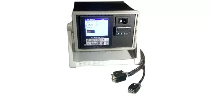
Temperature controller fails or becomes obsolete.
Compressor systems require service or.
Cryogenic cooling solenoid valves eventually wear out.
Everything else eventually.
New functionalities in automation and reporting seem impressive and may be worth the upgrade to something new but other than advances in Ethernet control there is not so much new I see on the front of test equipment or controller communication. Many people have valid reasons for sticking with GPIB but after at least a decade of being sure GPIB is on the way out, it is still viable and we still support it. Modern serial to USB converters make it much easier now and cheaper to communicate with multiple instruments when the cost of GPIB is seen as prohibitive.
Repair costs, especially for on-site work are always painful. Fortunately, thermal platforms/controllers can generally be sent-in to vendors for service. Often a new controller is less expensive than a repair on old equipment. The goal frequently is just getting aging systems operational for minimal cost – be it repair or replacement. Sometimes the goal is “More brains” or higher performance is preferred.
In any case, TotalTemp offers new systems, repairs on competitive brands, retrofit controllers, or maintenance parts.
Call us or email us, we will take your call, and we have the experience and care to support your thermal testing needs.
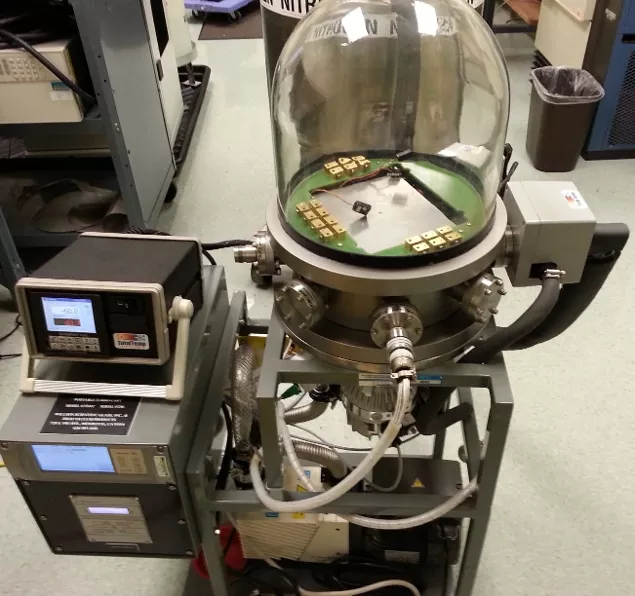
Space simulation adds another dimension to thermal testing. In vacuum environments, heat is transferred by radiation or conduction since transfer by air currents (convection) is of course not possible without air. This is easily accomplished using thermal platforms in portable TVAC systems.
As is the case with temperature chambers, space simulation systems are often sized considerably larger than required due to a lack of knowledge of what future requirements will be. This results in several inefficiencies.
Portable space simulation equipment is cheaper to acquire
Smaller systems don’t take up as much valuable lab space to use and to store when not in use
Faster to pull down to vacuum and fast temperature transition times result in shorter test times required to perform tests
They are more efficient, using less power, generally not requiring special electrical services
Smaller systems are often more time-efficient as you are less likely to have to share with others. Larger systems often require travel, time-sharing, and waiting for a scheduled-use time
Conclusion:
Thermal platforms are a piece of natural test equipment for space simulation.
Consider TotalTemp Technologies thermal vacuum systems for full range testing:
Temperature range +150 to -75C. Vacuum 10-6 Torr. For small to medium-sized devices. These thermal vacuum systems are flexible and fixture to meet many MIL-STD requirements.
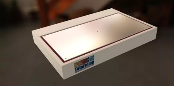
Larger, higher power items such as TWTs and amplifiers are easily accommodated with these 12″ x 24″ or 18″ x 25″ precision surfaces. They are also a good choice for larger or multiple Hybrid / MMICs. They have over 4000 watts of heat removal capability!
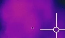
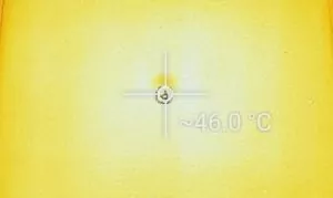
Thermal imaging reveals impressive uniformity of cooling. Model SD288 has six identical evenly distributed cooling channels. This ensures no hot spots or cold spots.
Likewise,16 linear heater elements ensure even heating.
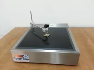
Larger modules can easily be tested right on the benchtop with an assurance of rapid test uniformity such as for meeting MIL-STD-883.
Programmable temperature control instrumentation with Multipoint DUT sensing module and advanced temperature control algorithms can automatically produce printed test logging results to a network printer and real-time reports in record time.
Test Stats are easily sent to email or text messaging systems.
Next time we will talk about the multichannel logging capabilities and advanced temperature control with the TE-1299-16, 16 channel logging accessory for the Synergy Nano.
Knowledgeable tech support at TotalTemp Technologies is available to help improve your thermal testing.
Simple automation of thermal testing saves time and money
Capitol Equipment and Tech time are always expensive… there are many costs involved with time spent waiting for a test to complete. Waiting for temperatures to be achieved is a big part of the time required for the thermal test. Frequently the time required for internal points of products to reach temperature is estimated, instead of measured. This ‘better safe than sorry approach often ends up unnecessarily extending the test time. It is a hedge against the flip side of erroneously reducing test times to less than what actually is required for internal temperatures to be achieved. Improperly cutting test time is also very costly. When failures that can be screened out with good testing make it into the field it is also expensive at many levels.
Modern temperature controllers can monitor one or more points of a Device Under Test (DUT). This easily speeds test time by verifying when additional slower responding points actually achieve the specified test temperature.
Thermal platforms increase the thruput rate of tests, reducing test time, energy costs and time spent tying up expensive test equipment. Valuable time is also saved time for the techs who are monitoring tests. Easily setting up automated notifications and printing or filing of test results create time savings.
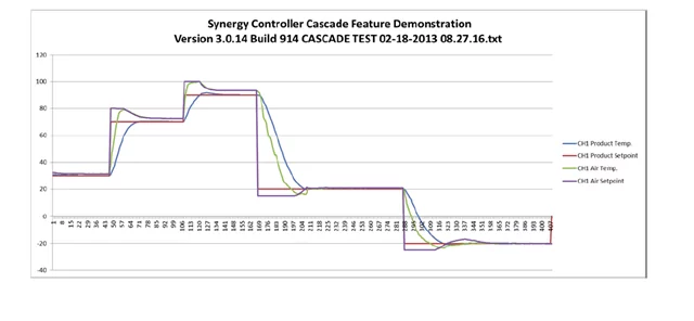
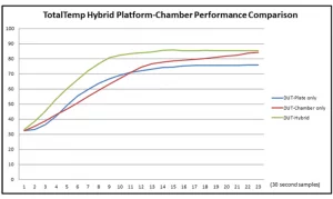
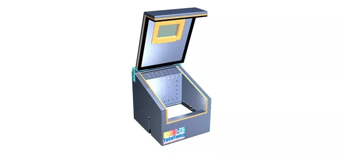
Since not all products have a nice flat conductive surface suited to testing on a thermal platform we introduced the Hybrid Benchtop Chamber that provides a ‘best of both’ solution, combining the universal capability of a temperature chamber with the conductive performance of a thermal platform. Gradients are reduced and speed is increased as benefits from the combination. Advanced temperature control algorithms are employed to speed ramping time and verify that specific internal sensors achieve specified temperature set points.
Contact TotalTemp to find out more about our fast and efficient thermal testing equipment.
What are the trade-offs of heat transfer via conduction versus convection in regards to thermal testing?
Heat transfer via conduction is generally faster and more efficient. Depending on your purposes, conduction has some clear performance advantages and some limitations which we will talk about. In general, however, when appropriate conduction is often the best choice for performance.
More to the point, in this discussion, we are talking about trade-offs between a temperature chamber and thermal platforms. Temperature chambers are an example of forced convection. Forced convection in a temperature chamber is achieved by the circulation of air using a fan.
Alternatively, natural convection is simply warmer air expanding and becoming less dense, naturally rising creating upward airflow with the colder air sinking to replace the heated air. As a practical note, some chambers have very little forced airflow and thus are limited in convection heat transfer performance. On the other hand, increasing airflow excessively can produce unwanted heating by air friction and wasted money and energy spinning large blowers.
For completeness, briefly here, Radiation as the third main method of heat transfer is typically only used for a thermal test where conduction or convection is not so practical such as thermal vacuum testing of products with non-flat surfaces.
A popular example of a comparison between conduction and convection is the pot on the stove.
Courtesy NASA / Machine Design
Mostly radiation transfers heat from the burner to the pan, convection transfers the heat within the water with hotter, less dense water rising and cooler water sinking until temperatures equalize. Conduction in this example will cause your finger to feel the heat and maybe prevent you from picking up the pan.
In the example of a temperature chamber, a fan augments the natural convection flow with stirring action, greatly increasing heat transfer, to be more precise, this is process is often known as advection. The convective heat transfer in the air of a chamber is far less effective due to the relative density of air compared to water. This shows up as a much lower heat transfer coefficient in heat transfer equations.
For those who think more clearly in terms of equations, here is a simplified comparison of the math behind the heat transfer.
For Conduction: Q = [k ∙ A ∙ (Thot – Tcold)]/d
Conduction is the direct diffusion of heat through a solid material
Q is the amount of heat transferred per unit of time
k is the thermal conductivity of the barrier
A is the heat transfer area
T-hot and T-cold are the temperatures of the regions for heat transfer
d is s the thickness of the barrier
With Convection, the Equation looks like this:
Convection is the heat transfer between two items via moving groups of molecules
Q = hc ∙ A ∙ (Ts – Tf)
Where Q is again the amount of heat transferred per time unit
Hc is the convective heat transfer coefficient
A is again the heat transfer area
Ts and Tf are the temperatures of the surface and the temperature of the fluid (air)
These equations describe natural convection heat transfer, not assisted by fan or stirrer. The equations become considerably more complex and generally subject to heuristics and detailed modeling in order to achieve at least moderate accuracy. Variables such as calculating the barrier layers at surfaces, determination of laminar v. turbulent flow and general calculations based on the geometry of the air space fit into the equations. All that boils down to the generality that the more you can stir the air the better the heat transfer – however, it will never be as good as conduction. The kitchen example here is that you may be able to keep your hand in a hot oven for a couple of seconds without getting burned but just a few milliseconds of conduction will cause ‘cutaneous damage’ to your finger so with this you can see the relative rate of heat transfer with conduction and convection.
Besides burning your finger, conduction has its issues as well. While the Heat transfer coefficient, hc is the main limiting factor for heat transfer by convection, area (A) is the main limiting factor for heat transfer by conduction on thermal platforms. Extra care must be taken as well to ensure that the area is really what you think it is(link). Often voids or irregular surfaces limit the area of actual contact.
TotalTemp’s solution to optimal heat transfer is with the intelligent combination of both conduction and convection (advection) in our new Hybrid Benchtop Chamber.
Feel free to contact us with any questions concerns or interest in thermal platforms Hybrid benchtop chambers or any thermal testing equipment. We are always available with quality before and after-sales support.
How tightly to clamp devices to a heatsink or Thermal Platform?
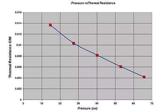
It is true that the more tightly you can clamp two surfaces together the better the heat transfer. This is especially important if you are looking to transfer large amounts of heat from one device to another.
Courtesy: OverClockers
If you are talking about small items that produce little or no heat, good contact is still important but the ultimate heat transfer efficiency really isn’t so critical. However, there are many cases such as dissipating the heat from millions of transistors in a CPU or high power output devices driving heavy loads, maximizing heat transfer can easily become critical. For thermal testing, it is always important to minimize temperature differences between part interfaces.
Along with the thermal conductivity, sufficient surface area and the flatness of both heat transfer surfaces clamping force are also important. If you think about it, remember that particularly if you are talking about a large surface area, what is important is the force per square inch.
Therefore larger items generally will require larger force and of course never more force than what would deform or distort the package that is looking to keep good contact with the heatsink or thermal platform. Also, higher wattage heat transfer will require better heat transfer that is possible with sufficient clamping.
Clamping Methods
Low force single-arm clamp
Dual arm clamp set
High force Kopal Clamp
The main methods of securing devices to thermal platforms are simply screwing the device to the surface, spring clamps, or other hand tightened types of clamps. We offer light, medium, and heavy-duty clamping systems. Platforms can be directly drilled or an adapter plate can be secured on top of the platform, Adapter plates slightly slow down the performance but allow flexible or interchangeable hole patterns for specific tasks or loads. Custom cutouts and pockets are also possible to allow optimal contact to irregular surface components without making custom modifications to the surface of the platform.
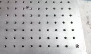
Custom Adapter Plate with an array of 4-40 holes
IN CONCLUSION:
While we carefully avoided equations and theoretical heat transfer equations in this write-up, If you are producing less than 5 watts per square inch or are OK with more than a 5-degree difference between the device package and platform or heatsink then light or no clamping at all may be required. From there up, the more wattage the more clamping force required. If for example if you are trying to transfer 50 watts per square inch, you may need 20 pounds per square inch clamping force. For more specifics, we are available to review and discuss more specifics of your heating and cooling requirements.
Top Reasons People Use Liquid Nitrogen for Thermal Test Cooling
Thermal testing can be time consuming. Getting it done in a reliable, verifiable way using less time means less costs.
Thermal Platforms heat and cool with conduction which is inherently faster than with convection in a temperature chamber.
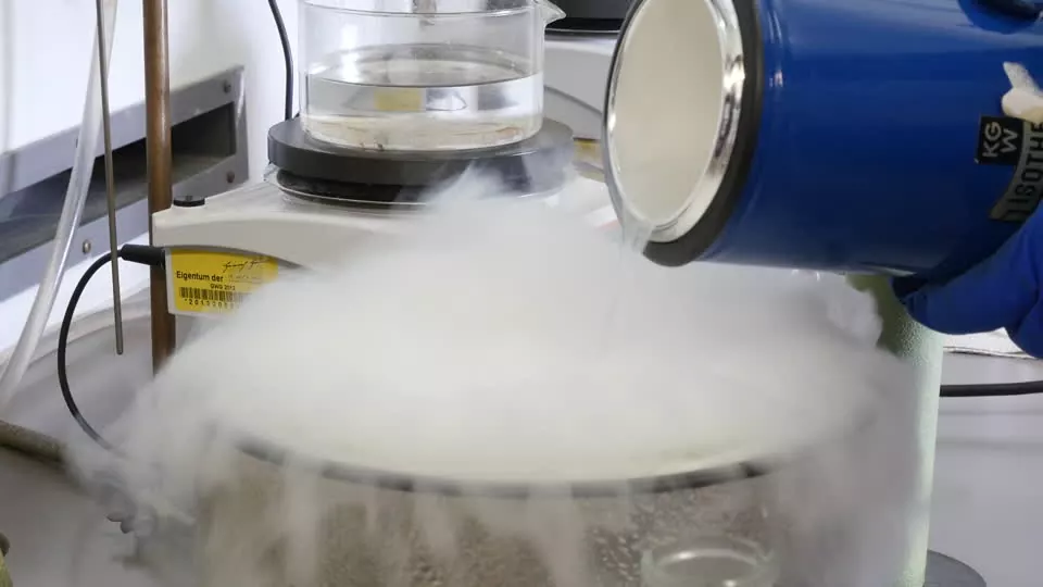
Coolant choices are detailed elsewhere in the TotalTemp Blogs but to make a long story short, The main prevailing cooling choices are – Refrigeration compressors and expendable refrigerants ie. Liquid Carbon Dioxide (CO2) and Liquid Nitrogen(LN2).
Liquid Nitrogen has the ability to provide the fastest ramp rates and achieve the coldest temperatures. Temperatures down to -100ºC or colder are achievable with ramp rates over 50ºC per minute. Typically the full range is not needed but in the event that future testing requires yet colder temperatures it is good to have the capability built in and not have to replace equipment.
LN2 systems are far simpler than refrigeration systems with many less ways they can fail.
LN2 cooling uses very little power so no special electrical services or usage costs are involved.
In my experience, LN2 delivered through a distribution system can have it’s issues but is often less troublesome than CO2 distribution systems. CO2 systems can sometimes have blockage issues revolving around 1) Water intrusion and 2) the physical property of CO2‘s triple point. Triple point is the temperature and pressure where CO2 can exist as liquid gas and solid. For CO2, this occurs at a relatively low pressure resulting in the possibility of coolant becoming solid (dry ice) in the delivery line or elsewhere besides the point of use.
Mechanical refrigeration systems are initially considerably more expensive than expendable coolants and in often in the long run are more expensive than expendable coolants when electricity usage and maintenance is included in the equation. Mechanical refrigeration is also far more complicated and expensive when temperatures below -35º or -40ºC are required. Modern refrigeration systems to achieve testing temperatures below -40 have evolved considerably but they are still extremely complicated more expensive and prone to requiring service.
I’d like to end on a positive note but first it would be fair to address the down side as I see it for using LN2 as a coolant. When smaller scale usage is the case, portable tanks make more sense, changing tanks out can be a nuisance but if usage is greater, a distribution systems would be in order. Distribution systems are fairly expensive, typically much more than $100/linear foot. Since LN2 is so incredibly cold, about -185ºC vacuum jacketed insulation is required to reduce losses. There will always be some losses in the delivery line with small or large LN2systems. Finally the biggest concerns with LN2 is the recommendation for an automated LN2 shut off valve to prevent run-away cooling in the event of a valve sticking open.
As an alternative to LN2 distribution systems, there are distribution systems using liquid CO2 that are designed with the ability to distribute the coolant through an uninsulated small diameter line thus reducing losses. Makers of CO2 distribution systems claim significant economy over LN2 delivery systems. However as a down side, a single refrigeration compressor must run to condense the coolant into a reservoir above the points of use.
So the the Top Reasons to use Liquid Nitrogen are 1) Speed of cooling, 2) Temperature range, 3) Low initial cost and 4) Favorable long term costs 5) Superior reliability.
As a manufacturer of thermal testing products, the majority of our requests are for LN2 cooled systems. Equally we offer CO2 cooled or mechanical refrigeration systems. We endeavor to help customers acquire the systems that best fill their testing requirements.
Call or email us now with any questions regarding your thermal testing
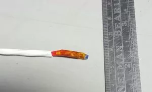
How to choose an appropriate temperature sensor for thermal test:
Selection criteria of an appropriate temperature sensor for a given application can be detailed but it often does not need to be that complicated. Two main points we are going to address today are sensor size and speed of response. Prior discussions covered thermocouple v. RTD and in the future, we will likely cover more of the environmental issues of temperature sensors such as temperature range and resistance to moisture or other abuse.
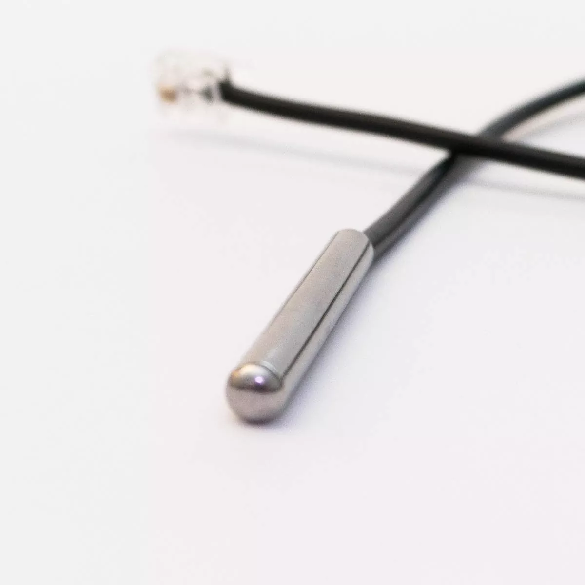
Small low mass sensor to screw-mount to the device surface
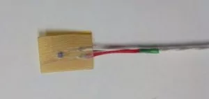
The sensor is typically used to sense Device Under Test. This sensor might be considered Medium-Massive and sensitive on both sides, results will show some smoothing of instantaneous temperature readings and although attached to the device there will be some weighted averaging with air temperature.
Thermocouples are by nature generally smaller, often cheaper, and lower mass but can be ultimately be packaged very much similarly to RTD sensors. Smaller, lower mass sensors will pretty much respond faster. When using a temperature sensor to control, the faster the response, generally the better. Likewise, when just logging a temperature fast response helps.
A slower response can solve or hide some other problems but often is it better to look more at the real problem. An example might be a sensor on a device being temperature conditioned on an uncovered thermal platform. The sensor may be subject to fluctuations in air temperature instead of the intended device. In this case, a cover is recommended as well as a sensor that is designed to be sensitive on one surface to reduce the possible negative effects of a sensor with a fast response.
Smaller, faster sensors although more fragile are often desired when a device under test is small relative to the sensor and when the temperature of a very specific location is desired instead of a larger package. You don’t want the sensor to be so big that it occurs as a heat sink to the device being monitored.
There are times when some temperature smoothing effects (smoothing over a surface area/volume and overtime) sensed by a more massive sensor is helpful but on the other hand, often modern monitoring/controlling systems can add response smoothing over time through software if averaging is required. There is generally limited ability to compensate for a slow response. Smoothing over a volume or surface is likely best monitored with larger or multiple sensors. Often once a device can be thermally modeled/characterized with multiple sensors, a single sensor can provide good test data for ongoing tests.
Inside a temperature chamber or on a thermal platform, the temperature reading of a device under test is often desired. Many systems now have advanced temperature control algorithms that rely on both the chamber (or platform) temperature plus the temperature of the device. If possible a small pocket or hole on the device to locate the temperature sensor, make good physical contact and isolate it from the air can be helpful as well as a sensor designed to be sensitive on just one surface. In many cases, a small rugged sensor with insulating adhesive tape on one side is a good choice for making good physical contact to take device temperatures. Some sensors such as the top two pictures have a small mounting hole used to secure the sensor to the device under test.
Adhesive mount RTD surface sensor
Many modern temperature instruments offer the ability to read several different types of sensors including RTDs and thermocouples however I have found that often the instruments are more optimized for one range or one type of sensor than another.
We previously indicated our preference for RTDs over thermocouples, we stand by that opinion but there are also some very high-quality thermocouples that remain accurate and repeatable over a range of abusive conditions such as extreme temperatures or rapid ramping rates and vibration. We additionally generally find that the RTD sensors made of wound platinum wire are more durable than those which are made with platinum wire printed on a substrate.
100 ohm DIN RTD element made of platinum plating on the substrate.
Temperature sensors designed to measure air temperature can be elaborate with fins or special materials to transfer heat from the air but often work best in a simple thin-walled aluminum sheath to protect the sensor from contamination and abuse. A small amount of conductive grease inside helps improve heat transfer from the sheath to the sensor element inside. Likewise, a small amount of thermal grease between the sensor housing and the device under test is helpful.
Some POINTS TO REMEMBER specifying a temperature sensor.
Small size and speed optimized for the size of the device under test and controller
Review best compatibility with instrumentation and device
Ability to attach to the device to be sensed
Low mass v. ruggedness of sensor for repeated usage
A final note:
There are a wide variety of temperature sensors available, generally smaller is better for faster response, large enough to make contact with the surface you really want to measure but not so big that there are resulting lags in the readings. Let TotalTemp’s many years of experience help you select the right sensor for measuring the temperature of your device to be tested.
Applying Purge Gas Provides Two Main Benefits When Thermal Testing
INTRODUCTION:
A choice to be considered when selecting the best thermal test system is the use of purge gas. Purging with gas serves two purposes during environmental thermal testing. Most often it is used to keep condensation and frost from accumulating on the surfaces of the DUT (Device Under Test) at cold temperatures. Additionally, it is also used to prevent the oxidation of metals surfaces at high temperatures.
Heavy frost forming at -40C ultimately becomes wet.
High-temperature corrosion
Generally, the condensation of any moisture is to be avoided during the environmental testing of electronics.
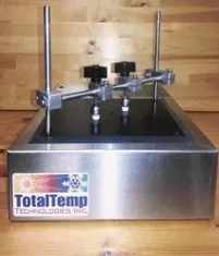
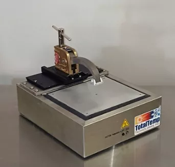
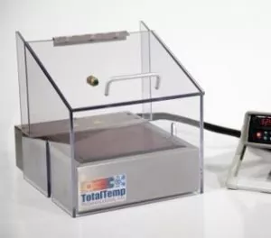
Thermal Platform with Probing Cover & Nitrogen(g) Inlet
In simple terms, condensation occurs when the air temperature drops below the dew point. Above the dew point, more moisture evaporates from surfaces than condenses, below the dew point more water condenses on surfaces than evaporates. The dew point is a temperature determined by the combined effects of the surface temperature and the relative moisture content of the air (assuming the same atmospheric pressure).
Generally, condensation is to be avoided during the environmental testing of electronics. In simple terms, condensation occurs when the air temperature drops below the dew point. Above the dew point, more moisture evaporates from surfaces than condenses, below the dew point more water condenses on surfaces than evaporates. Thus, the farther below the dew point, the faster moisture will condense. The Dew point is a temperature point that is determined by the combined effects of the surface temperature and the relative moisture content of the air (assuming the same atmospheric pressure).
The easiest way to avoid condensation on a DUT is to lower the moisture content of the air. The easiest way to do that is with dry Nitrogen purge gas into the space around the DUT. The Nitrogen displaces moisture-laden air so that dew point condensation of high-temperature oxidation cannot occur. Nitrogen from a Dewar or portable tank works very well because the moisture content of the Nitrogen is extremely low and it is often readily available at the test station. Nitrogen is also notably inert, that is to say, it does not easily react with other elements or materials. If you are going to extreme temperatures and condensation can cause problems with your devices, you should take measures such as purging gas to reduce condensation. Critical or sensitive metal surfaces exposed to hot temperatures above 170C will be preserved better with purge gas as well.
Sometimes the question comes up if CO2 (Carbon Dioxide) can be used as a purging gas. The quick answer is no. Although CO2 from a tank is dry and displaces moist air, CO2 can react with water to produce carbonic acid which of course is corrosive. As long as there is no moisture, to begin with, CO2 would work but it is generally not recommended. Other gasses such as Argon can also be used but are generally more expensive. If your facility provides clean dry compressed air, often this can be successfully used to purge, especially if your air is really dry (some facilities add a desiccator system to air supply) and temperatures are not so extreme (~above -20° C as a rule of thumb).
Your requirements may vary but as a starting point in a small benchtop enclosure or chamber 15 – 20 SCFM for an initial flow rate to displace moist air followed by a reduced rate of 3-5 SCFM two to three minutes after openings have been closed. Too much flow on an ongoing basis can create air temperature gradients inside the box.
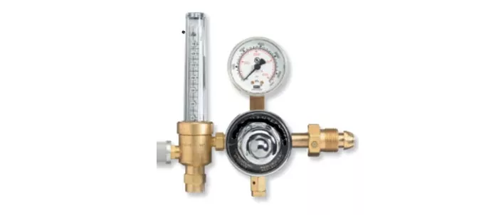
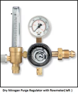
Consult your application engineer about options to automate these processes. Application of purge gas to a thermal platform or chamber is generally very easy. A pressure regulator can attach right to your Nitrogen tank. The flowmeter is normally located at the tank as well and is used to set the flow rate. Typically a small 1/4″ OD uninsulated hose can connect the output of the regulator/flowmeter to the hot-cold plate cover or chamber with a simple push to connect fittings.